Artificial knee joint

a knee joint and artificial knee technology, applied in knee joints, prostheses, medical science, etc., can solve the problems of inability to forget the rotation problem of the artificial knee, slipping easily, and often destroying the function of the ligament, so as to reduce abrasion, prevent slipping, and facilitate rotation

Inactive Publication Date: 2010-03-16
NAKASHIMA PROPELLER +1
View PDF28 Cites 138 Cited by
  • Summary
  • Abstract
  • Description
  • Claims
  • Application Information

AI Technical Summary

Benefits of technology

[0009]The problems to be solved by the present invention is to provide smooth movement, readily induce rotation and make it possible to reduce abrasion and guarantee strength by skillfully devising the shape and placement of the post and cam taking into consideration the specific relationship between the post and intercondylar groove and the specific relationship between the condyles and the articular surfaces.
[0017]With the above structure of the artificial knee joint of the present invention, rotation is induced as a result of the femur and the tibia flexing, that is, the femoral component and the tibial component turning. Thus, when rotation is spontaneously induced during flexion of the artificial knee joint, ligament balance is no different from that of a biological knee joint, smooth motion from the joint becomes possible, and it becomes possible to cope with the deep flexion actions unique to Japanese, including the formal way of sitting with one's legs folded and sitting cross-legged. The present invention provides specific shape and placement of the post and cam for inducing rotation. In the present invention, turning is induced from the early stages of rotation, and interference between the medial side surface of the intercondylar groove and the post at this time is prevented, abrasion is reduced, and smooth movement is realized. Furthermore, the cam rotates smoothly with respect to the post, contact surface area is increased, and abrasion is reduced. In addition, turning is induced over the entire angle of flexion.

Problems solved by technology

The collateral ligaments and the anterior and posterior cruciate ligaments regulate this slipping to the front and back or left and right, but this ligament function is often destroyed or weakened and slipping readily occurs in patients that are suitable candidates for artificial knee replacement.
On the other hand, the problem of rotation with the artificial knee cannot be forgotten.
However, later research revealed that the PS-type artificial knee has other problems.
More specifically, the post and the side surfaces of the intercondylar groove interfere with one another due to rotation during flexion.
The post is worn by the interference and the powder from this abrasion invades bones and other tissues, causing them to dissolve and break down biologically.
However, as a result, there is a reduction in strength of the post and the post may break.

Method used


Image

  • Artificial knee joint
  • Artificial knee joint
  • Artificial knee joint

Examples


Embodiment Construction

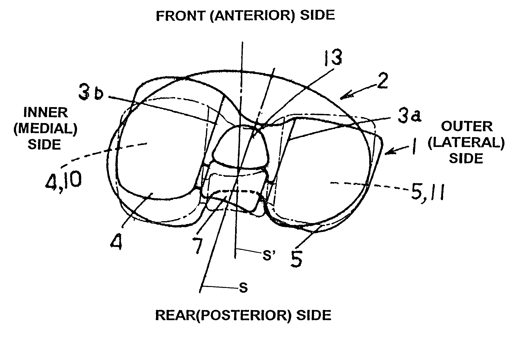
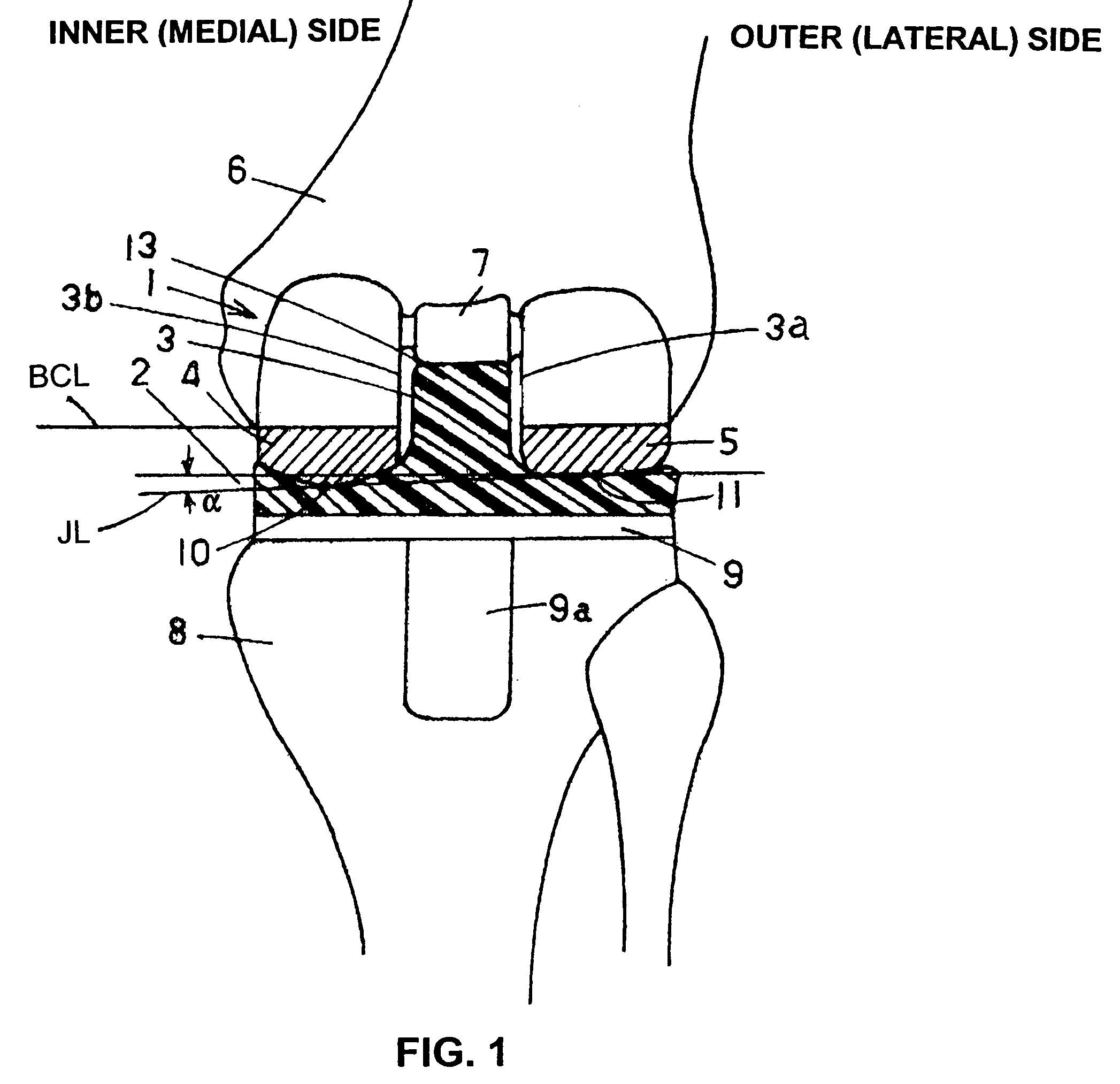
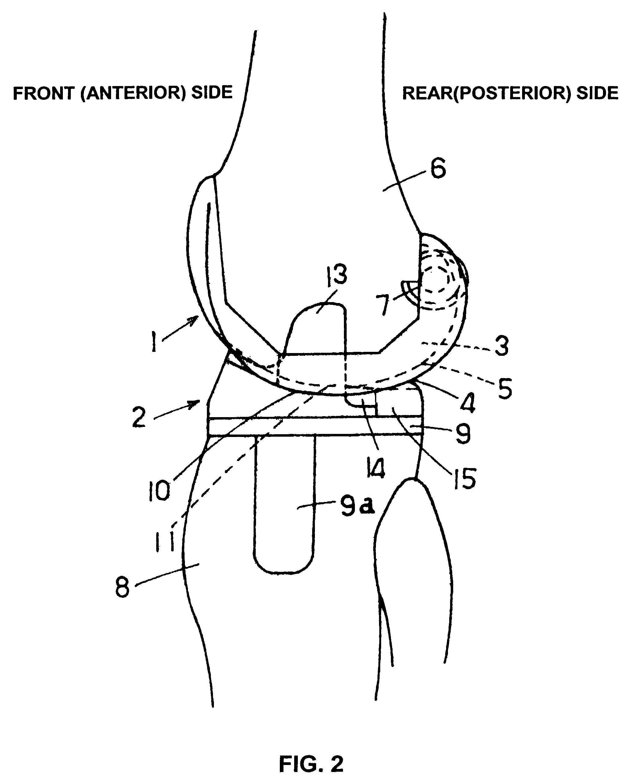
[0025]The present invention will be described below in detail with reference to the preferred embodiments while referring to the drawings. FIG. 1 is a side view of an attached artificial knee joint in standing position as an example of the present invention. FIG. 2 is a cross section of a rear view of the same.

[0026]The artificial knee joint of the present invention is a combination of femoral component 1 and tibial component 2. The femoral component 1 is made from titanium alloy or another biocompatible metal; and it has inlet-shaped intercondylar groove 3 extending from the posterior end to near the anterior end disposed in the center and medial condyle 4 and lateral condyle 5 formed to substantially the shape of the letter C by the side view. The femoral component 1 is attached to the distal end of femur 6. The outline of medial condyle 4 and lateral condyle 5 is convex from the front to the back, and this convex shape is longitudinally contiguous in a stripe.

[0027]It should be n...


PUM


Abstract

An artificial knee joint including a femoral component and a tibial component which are in relation of making relative rotation, in which the tibial component has a post that has an outwardly curving posterior surface and is disposed approximately in the longitudinal center between the articular surfaces so that the post is inside an intercondylar groove that is between the medial and lateral condyles and extends from the posterior end to the anterior end of the femoral component; and the femoral component has a cam that is disposed at the posterior portion of the intercondylar groove and comes into contact with the posterior surface of the post when the above-described rotation proceeds; and the post and the cam are shaped so that the femoral component is turned outwardly when the cam comes into contact with the post as a result of the rotation and as the rotation proceeds.

Description

PRIORITY DATE[0001]This application claims foreign priority to 2004-75903, filed Mar. 17, 2004.BACKGROUND OF THE INVENTION[0002]1. Technical Field[0003]The present invention relates to an artificial knee joint to replace a knee joint.[0004]2. Description of the Related Art[0005]Artificial knee joint replacement is performed in cases in which the knee is afflicted by osteoarthritis, rheumatoid arthritis, or bone tumor, or is subjected to trauma and the like. This artificial knee is a combination of a femoral component that is to be attached to the distal end of the femur and has a medial condyle and lateral condyle and a tibial component that is to be attached to the proximal end of the tibia and has a medial articular surface and a lateral articular surface that support the medial condyle and lateral condyle, respectively. However, both of these condyles and articular surfaces must perform the same movements as a biological knee.[0006]More specifically, when the knee is flexed, the ...

Claims


Application Information

Patent Timeline
Patent Type & Authority Patents(United States)
IPC IPC(8): A61F2/38A61F2/64
CPCA61F2/3886
Inventor SUGURO, TORUKURAMOTO, KOICHIYAMAMOTO, KEITARO
Owner NAKASHIMA PROPELLER
Why Eureka
Try Eureka