
Feeding clip

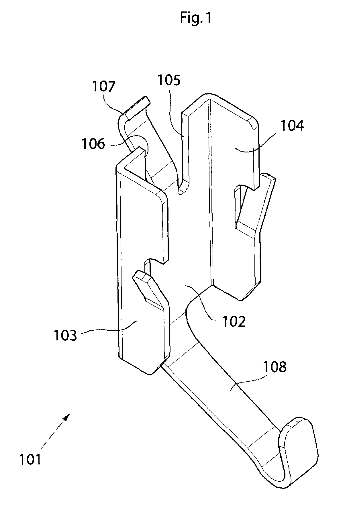
a technology of feeding clip and assembly, which is applied in the direction of coupling device details, fixed connections, coupling device connections, etc., can solve the problems of plurality of details, complicated above-mentioned pogo pins, and relatively high use costs of pogo pins, so as to reduce the pathway for rf-signals in the feeding clip and shorten the height

Inactive Publication Date: 2010-03-16
SAMSUNG ELECTRONICS CO LTD
View PDF13 Cites 2 Cited by
  • Summary
  • Abstract
  • Description
  • Claims
  • Application Information

AI Technical Summary

Benefits of technology

The present invention provides an improved antenna assembly and feeding clip for mobile communication devices that overcomes various problems associated with conventional antenna assemblies. The invention provides a solution that allows for a shorter electrical pathway between the feeding point on the printed circuit board and the radiating structure of the antenna assembly, while also providing more space for the radiating structure. The feeding clip is designed to have excellent electrical characteristics and mechanical strength, and is suitable for assembly processes. The invention also provides a more efficient use of space on the printed circuit board, allowing for more contact areas and reducing the pathway for RF-signals in the feeding clip. Overall, the invention provides a more effective and efficient solution for improving antenna assemblies in mobile communication devices.

Problems solved by technology

The above mentioned pogo pins are rather complicated, including a plurality of details, and their sockets may have to be soldered to a component in the communications device.
Thus, the use of pogo pins is relatively expensive.
Another problem with prior art connectors using a helical spring or the like is that the electrical parameters, notably inductance and capacitance, vary with the length of the spring.
Thus, in some applications in which the spring is compressed, this compression creates unwanted variations in the RF characteristics.
Another drawback with some prior art solutions is that the connector device occupies space that otherwise could be used as an effective radiating area of a radiating element.

Method used


Image

  • Feeding clip
  • Feeding clip
  • Feeding clip

Examples


Embodiment Construction

[0055]In the following description, for purposes of explanation and not limitation, specific details are set forth, such as particular techniques and applications in order to provide a thorough understanding of the present invention. However, it will be apparent to one skilled in the art that the present invention may be practiced in other embodiments that depart from these specific details. In other instances, detailed descriptions of well-known methods and apparatuses are omitted so as not to obscure the description of the present invention with unnecessary details.

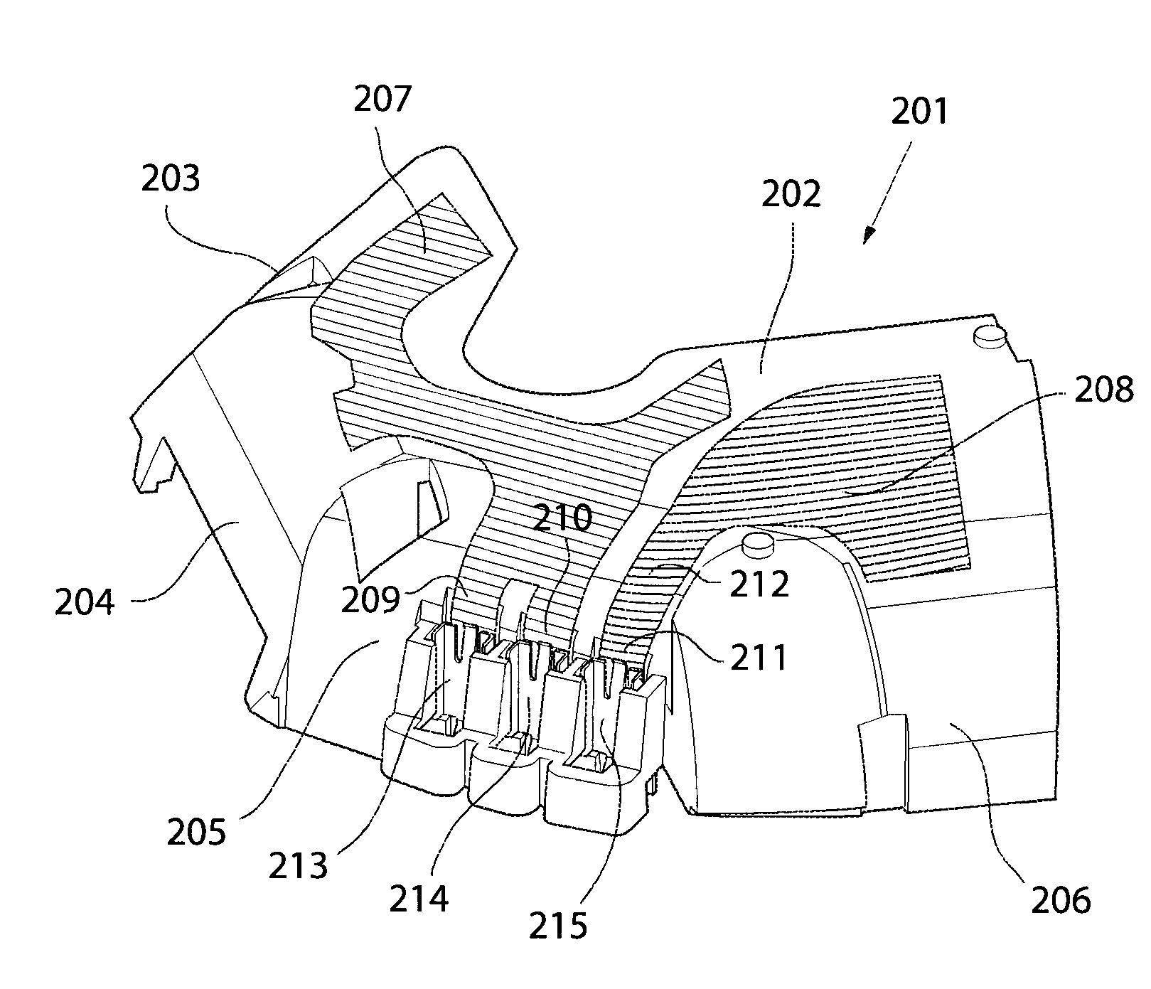
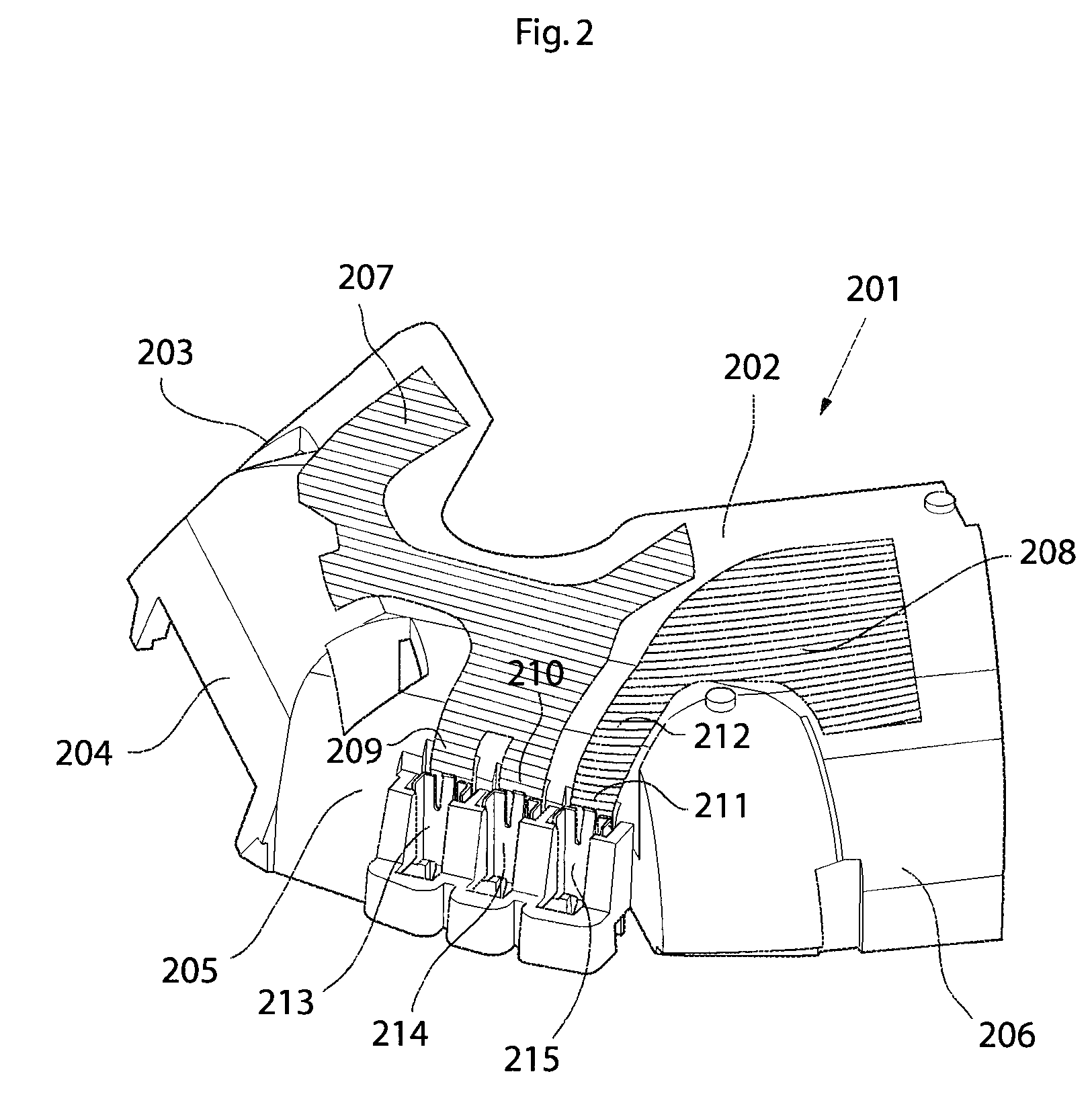
[0056]FIG. 2 is a schematic view in perspective of an antenna assembly according to on aspect of the present invention. A support structure 201 is moulded into a predetermined shape to fit in a mobile communication device (not shown). The support structure 201 is to be mounted on a PCB, printed circuit board (not shown), of the mobile communication device. The support structure 201 comprises a top part side 202 and seve...


PUM


Abstract

The present invention relates to an antenna assembly comprising a support structure for carrying a radiating structure and at least one feeding clip, the antenna assembly is provided to be mounted on a PCB in a mobile communication device, the support structure comprises a top side part which is to be mounted substantially parallel with the PCB, the top side part is positioned, when mounted on the PCB, at a first distance from the PCB, and the radiating structure comprises at least one contact area located on the support structure. The antenna assembly is characterised in that the contact area for the radiating structure is located at a position on the support structure where a distance between the contact area and the PCB is less than the distance between said top side part and the PCB. The invention also relates to a feeding clip.

Description

TECHNICAL FIELD[0001]The present invention relates to an antenna assembly and a feeding clip. More specifically the present invention relates to an antenna assembly and a feeding clip for effective electrical coupling of RF signals between circuitry in a mobile communication device and the antenna assembly as well as effective use of available space.BACKGROUND OF THE INVENTION[0002]As portable radio communication devices, such as mobile phones, become smaller the electronic components contained within the devices, e.g. antennas, will also need to be smaller. The electrical connection of these components is realized by means of connectors, which shall provide good and well defined electrical contact and which should be insensitive to small variations in manufacturing dimensions.[0003]Therefore, elastic type or spring type of connector is becoming increasingly attractive for small components. Such connectors are known to provide reliable electrical connection. Spring features provide ...

Claims


Application Information

Patent Timeline
Patent Type & Authority Patents(United States)
IPC IPC(8): H01Q1/24H01Q1/50H01R12/55H01R12/57
CPCH01Q1/1207H01Q9/0421H01Q1/243H01Q1/20
Inventor NILSSON, JONASSTARCK, JONAS
Owner SAMSUNG ELECTRONICS CO LTD
Learn More