Mobile millimeter wave communication link

a technology of millimeter wave and communication link, which is applied in the direction of transmission monitoring, wireless commuication services, substation equipment, etc., can solve the problems of high inability to justify the cost and long construction period of fiber optic trunk lin

Inactive Publication Date: 2010-03-16
TREX ENTERPRISES CORP
View PDF7 Cites 237 Cited by
  • Summary
  • Abstract
  • Description
  • Claims
  • Application Information

AI Technical Summary

Problems solved by technology

However, the construction of fiber optic trunk lines is expensive (sometimes very expensive) and the design and the construction of these lines can often take many months especially if the route is over private property or produces environmental controversy.
Often the expected revenue from the potential users of a particular trunk line under consideration does not justify the cost of the fiber optic trunk line.
Current state of the art mobile communications links using radio frequency (RF) or microwave communications have fairly loose pointing tolerances, but tend to be limited in data rate to speeds of 45 Megabits per second (Mbps) or less.
Current state of the art communications using lasers can support higher data rates of 1.25 Gibabits per second (Gbps) and higher in good weather, but perform poorly in adverse weather conditions.
These systems typically use narrow beams with divergences on the order of 0.1 degrees or less, and thus laser link transceivers must be pointed very accurately, which is challenging on a moving platform.

Method used


Image

  • Mobile millimeter wave communication link
  • Mobile millimeter wave communication link
  • Mobile millimeter wave communication link

Examples


Embodiment Construction

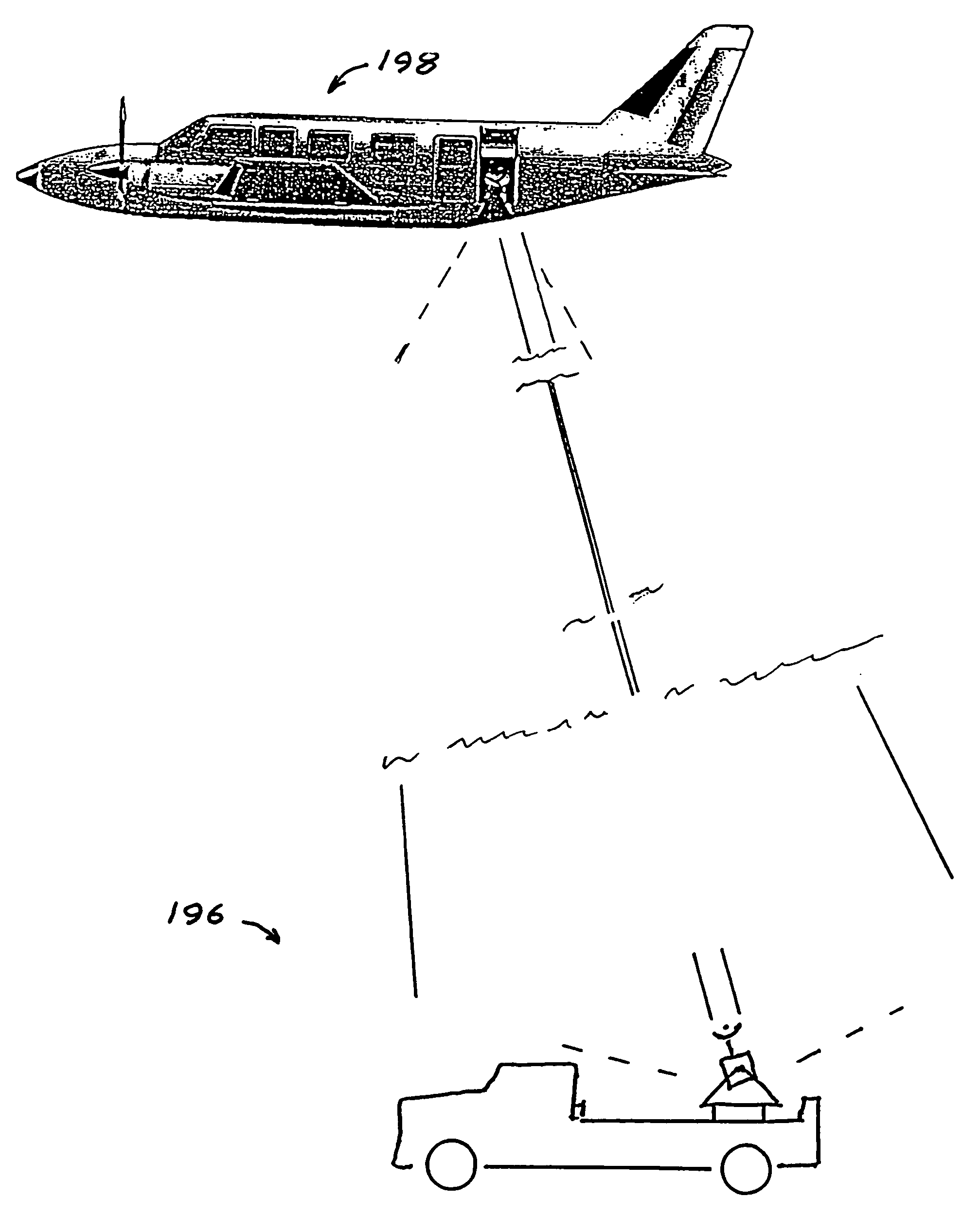
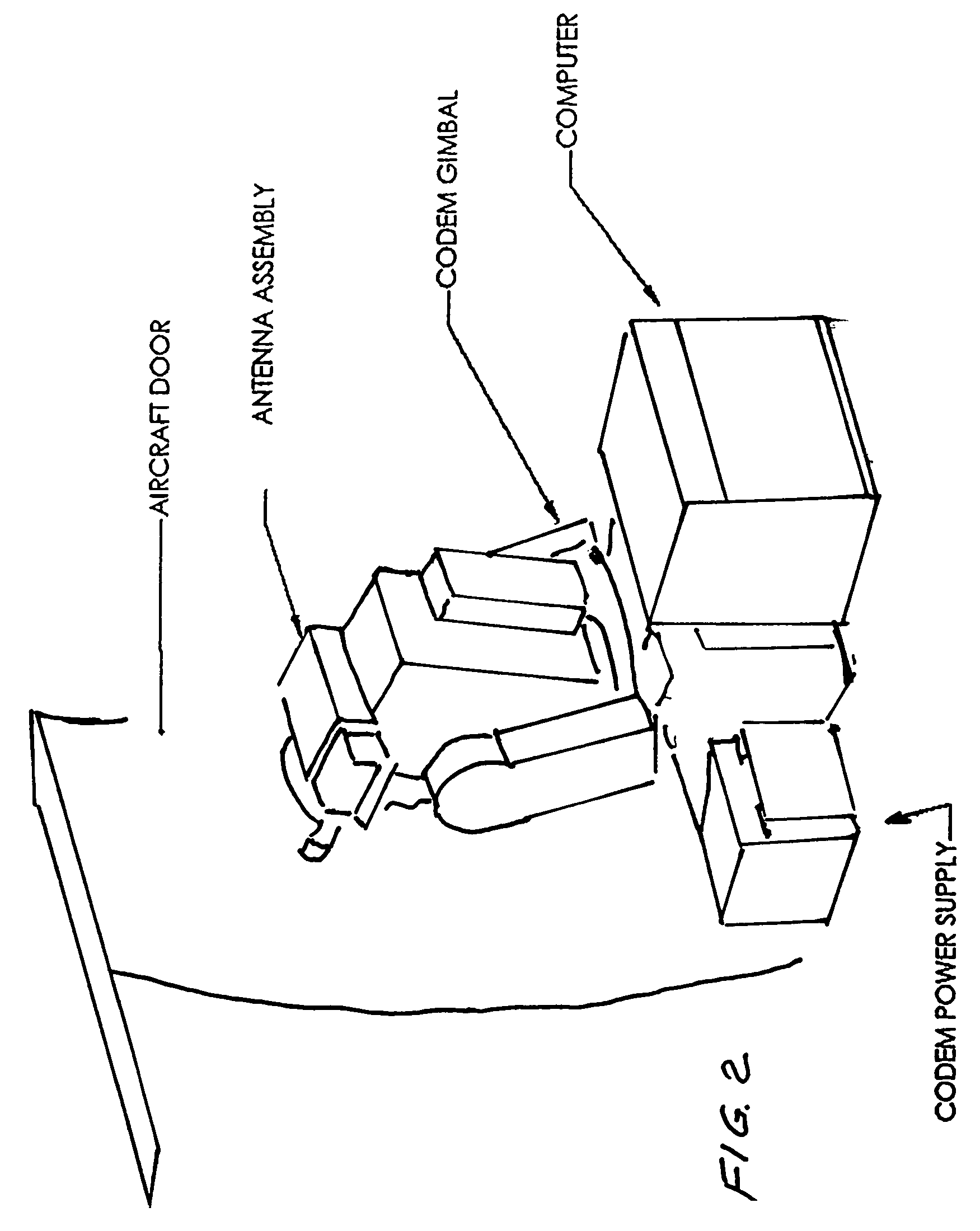
[0044]First Preferred Embodiment Mobile Air to Stationary Ground Platform Important antenna pointing features of a first preferred embodiment of the present invention are shown in FIGS. 2 and 3 and 5 through 8. This embodiment represents a prototype demonstration carried out by Applicants to prove many of the advantages of the present invention. It is a mobile-to-stationary link, specifically a mobile aircraft station 198 to stationary ground station 196 as shown in FIG. 3. A view of the aircraft gimbaled transceiver looking out the aircraft window is in FIG. 2. The main components of the gimbaled aircraft transceiver are shown in the FIG. 5 block diagram and the main components of the gimbaled ground transceiver are shown in FIG. 6. The aircraft is a Piper Navajo PA31-350 and the regular luggage door was replaced with a door fabricated from Plexiglas that is about 90 percent transparent to millimeter wave radiation. The aircraft transceiver system 200 (FIG. 5) includes a 12 inch an...


PUM


Abstract

A point-to-point, wireless, millimeter wave communications link between two stations at least one of which is a mobile station. A millimeter wave transmitter system operating at frequencies higher than 57 GHz with a tracking antenna producing a beam having a half-power beam width of about 2 degrees or less and a millimeter wave receiver also with a tracking antenna having a half-power beam width of about 2 degrees or less. In preferred embodiments each mobile station has a global position system (GPS) and a radio transmitter and both tracking antennas are pointed utilizing GPS information from the mobile station or stations. The GPS information preferably is transmitted via a low frequency, low data rate radio. Each millimeter wave unit is capable of transmitting and / or receiving, through the atmosphere, digital information to / from the other station at rates in excess of 155 million bits per second during normal weather conditions. In preferred embodiments actually built and tested by Applicants digital information has been transmitted at rates of 1.25 gigabits per second. Preferred communication links described here are millimeter wave links operating at frequencies of 71-73 GHz and 74-76 GHz mounted on simple two-axis gimbals. Pointing information of the required accuracy is provided by GPS receivers and standard radio links which send the GPS calculated positions to the millimeter wave systems at the opposite end of the link. In these embodiments there is no need for any complicated closed loop pointing information derived from received signal intensity or phase. On moving platforms locally generated inertial attitude information is combined with the GPS positions to control pointing of the gimbaled transceivers.

Description

CROSS REFERENCE TO RELATED APPLICATIONS[0001]This application is a continuation-in-part application of Ser. No. 10 / 046,348 filed Oct. 25, 2001 now abandoned which was a continuation-in-part application of Ser. No. 09 / 847,629 filed May 2, 2001, now U.S. Pat. No. 6,556,836, Ser. No. 09 / 872,542 filed Jun. 2, 2001 now abandoned, Ser. No. 09 / 872,621 filed Jun. 2, 2001 now abandoned, Ser. No. 09 / 882,482 filed Jun. 14, 2001 now U.S. Pat. No. 6,665,546, Ser. No. 09 / 952,591, filed Sep. 14, 2001 now U.S. Pat. No. 6,714,800, and Ser. No. 09 / 965,875 filed Sep. 28, 2001 now abandoned. This application is also a continuation in part of Ser. No. 10 / 061,872 filed Jan. 31, 2002 now abandoned, Ser. No. 10 / 127,886 filed Apr. 23, 2002 now abandoned, Ser. No. 10 / 196,486 filed Jul. 15, 2002, Ser. No. 10 / 319,058 filed Dec. 12, 2002 now U.S. Pat. No. 7,065,326, Ser. No. 10 / 799,225 filed Mar. 12, 2004 now U.S. Pat. No. 7,062,293 and Ser. No. 10 / 859,006 filed Jun. 2, 2004 now abandoned. All of the above appl...

Claims


Application Information

Patent Timeline
Patent Type & Authority Patents(United States)
IPC IPC(8): H04M1/00
CPCH04B1/38H04B7/18504
Inventor LOVBERG, JOHNLILLY, DAVIDKOREVAAR, ERICCHEDESTER, RICHARD
Owner TREX ENTERPRISES CORP
Why Eureka
Try Eureka