Cooling, condensation and freezing of atmospheric water or of a microfluidic working-material in or on microfluidic devices

a microfluidic working-material and atmospheric water technology, applied in the field of cooling, condensation and freezing of atmospheric water or of a microfluidic working-material, can solve the problems of clogging of tiny nozzles and orifices, and affecting the quality of microfluidic devices

Inactive Publication Date: 2010-03-23
SLIWA JR JOHN W +1
View PDF4 Cites 25 Cited by
  • Summary
  • Abstract
  • Description
  • Claims
  • Application Information

AI Technical Summary

Benefits of technology

[0023]G. The use of freezing, whether or not condensed water is also frozen, to create structurally useful ice plugs or films, such as for providing a

Problems solved by technology

Despite all of the investment in microfluidic devices, there are still some fundamental issues and challenges that have not been overcome to anyone's satisfaction.
Tiny nozzles and orifices tend to clog if they dry out or if they are contaminated during nozzle self-servicing steps involving wipers or scrapers.
The trends toward jetted pigment-based inks and biological fluids are only making matters worse.
If the face of the printhead becomes fouled, then the orifice ink wets out onto the surface and causes misfires and unwanted deflection of droplets.
In particular, outgassing of ink and ingress of atmospheric gas can cause blocking bubbles in fine channels.
Even inks with water-retention features such as glycol or hydrop

Method used


Image

  • Cooling, condensation and freezing of atmospheric water or of a microfluidic working-material in or on microfluidic devices
  • Cooling, condensation and freezing of atmospheric water or of a microfluidic working-material in or on microfluidic devices
  • Cooling, condensation and freezing of atmospheric water or of a microfluidic working-material in or on microfluidic devices

Examples


Embodiment Construction

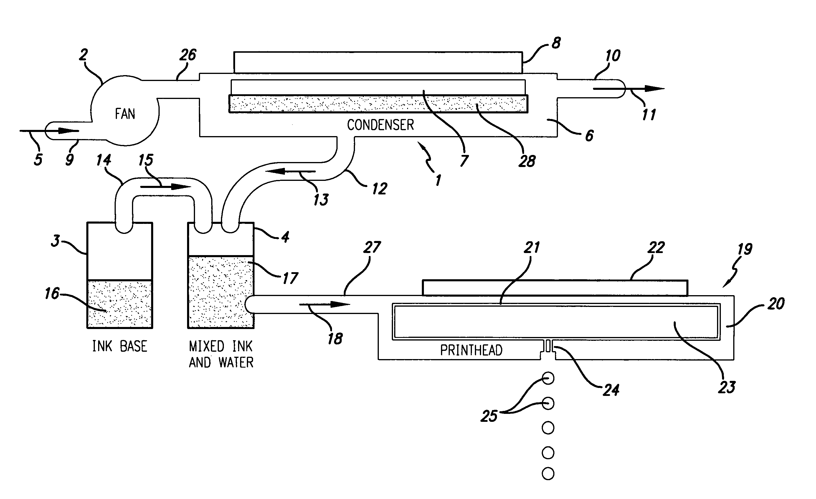
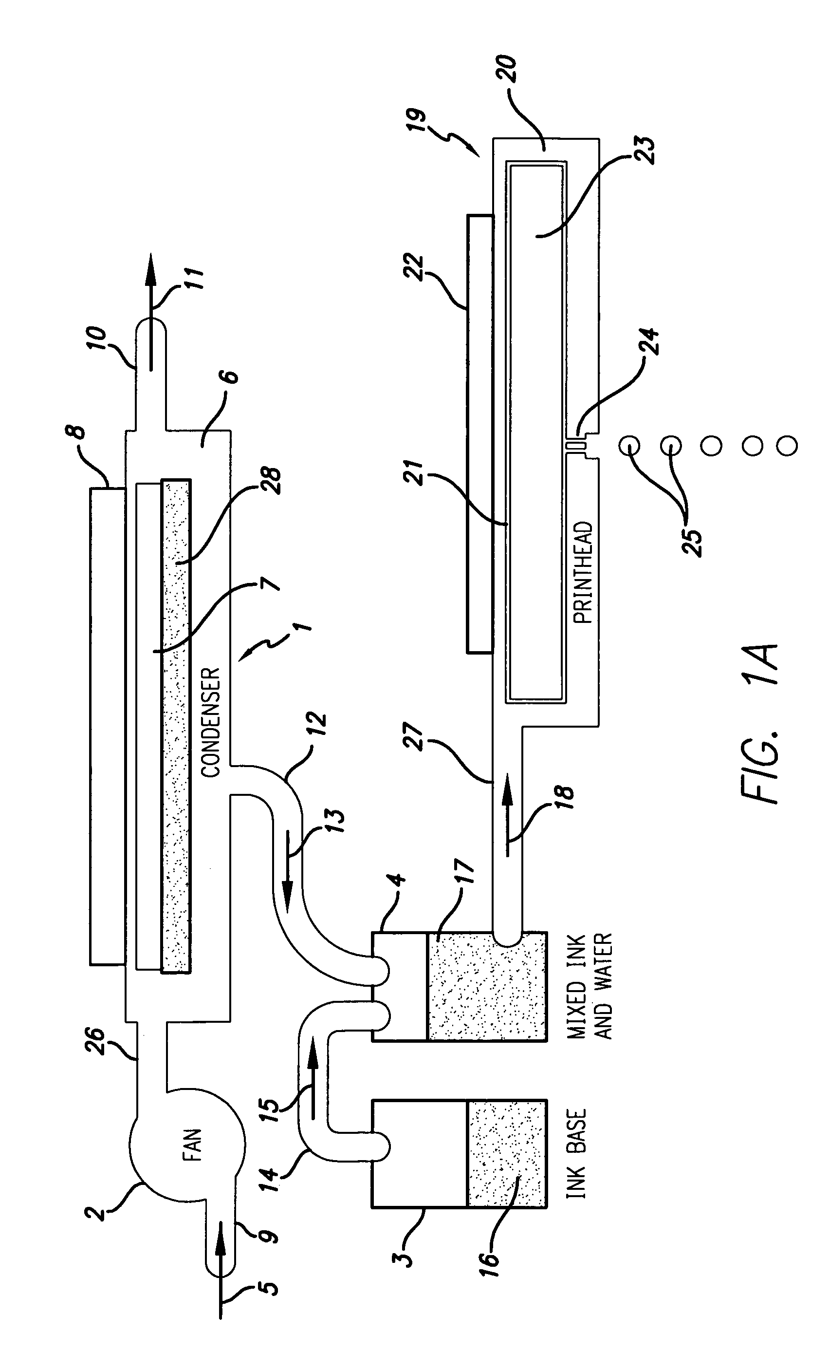
[0050]Moving now to FIG. 1A, we see a water-condensation unit 1 whose condensed water is routed, ultimately, to a microfluidic printhead 19. A fan 2 is shown drawing inwards ambient air in the form of flow 5 through conduit 9 and passing it into output conduit 26. Conduit 26 feeds into condenser 1. The structure of water condenser 1 includes a body 6 having a chamber 7. A cooling or chilling means 8 is thermally coupled to the chamber 7. The cooling means 8 could, for example, be a semiconductor-type electronic junction solid-state cooling chip (e.g., a thermojunction), which is preferred, or could be a known expansion nozzle refrigerator subsystem. Condenser 1 is depicted having a gaseous output conduit 10 with an outflow 11. In essence, ambient air 5 is drawn into the condenser 1 and has liquid water 28 condensed out of it. The drier air is then exhausted out conduit 10 as flow 11. It will be noted that condensate water 28 preferably sits in chamber or reservoir 7. Those familiar ...


PUM


Abstract

Condensation of water from a gas, such as from atmospheric air or other nearby ambient gas, is provided for use in a variety of jetting devices, such as inkjet and lab-on-a-chip applications. Further embodiments involve the use of frozen liquids, not limited to frozen condensed water, and microcooling of fluidic components or working materials for improved process control and reliability.

Description

CROSS-REFERENCE TO RELATED APPLICATION[0001]The present application claims priority from provisional application Ser. No. 60 / 576,047, filed Jun. 1, 2004.BACKGROUND OF THE INVENTION[0002]There is an ongoing application-explosion involving the manipulation and management of microscopic quantities of fluids for useful purposes. No application serves as a better example than the numerous permutations of inkjet-printers for commercial and personal printing applications that employ inks or marking materials. A multitude of methods for creating droplets and transferring them to substrates such as paper in desired patterns are known and many others are under development. The known methods include thermal-jetting drop-on-demand, piezo-jetting drop-on-demand, and pressurized continuous inkjets with electrical droplet steering. New methods under development and seen in the patent literature include ballistic aerosol printing and ballistic aerosol printing with gas flow droplet-deflection. Ther...

Claims


Application Information

Patent Timeline
IPC IPC(8): B41J2/17
CPCB41J29/377
Inventor SLIWA, JR., JOHN W.TOSAYA, CAROL A.
Owner SLIWA JR JOHN W
Why Eureka
Try Eureka