Method for separating/recovering oxygen-rich air from air, its apparatus and gas separation membrane module

a technology of oxygen-rich air and gas separation membrane, which is applied in the direction of membranes, filtration separation, separation processes, etc., can solve the problems of requiring extra components and/or structures, reducing the efficiency of the method of feeding pressurized air, etc., to achieve the effect of efficient separation and recovery of oxygen-rich air

Inactive Publication Date: 2010-03-23
UBE IND LTD
View PDF11 Cites 12 Cited by
  • Summary
  • Abstract
  • Description
  • Claims
  • Application Information

AI Technical Summary

Benefits of technology

[0015]According to the present invention, a simple spiral type gas separation memb...

Problems solved by technology

Such a spiral type gas separation membrane module has a simple structure and can be easily manufactured, but gives a low concentration of a separated/recovered gas because of a lower separation efficiency in comparison with a hollow fiber type gas separation...

Method used


Image

  • Method for separating/recovering oxygen-rich air from air, its apparatus and gas separation membrane module
  • Method for separating/recovering oxygen-rich air from air, its apparatus and gas separation membrane module
  • Method for separating/recovering oxygen-rich air from air, its apparatus and gas separation membrane module

Examples


reference example 1

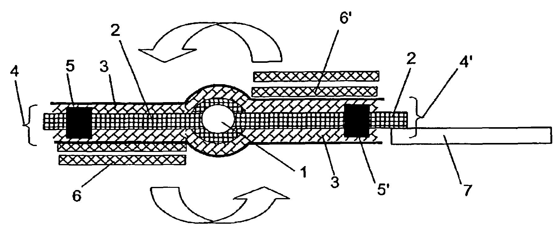
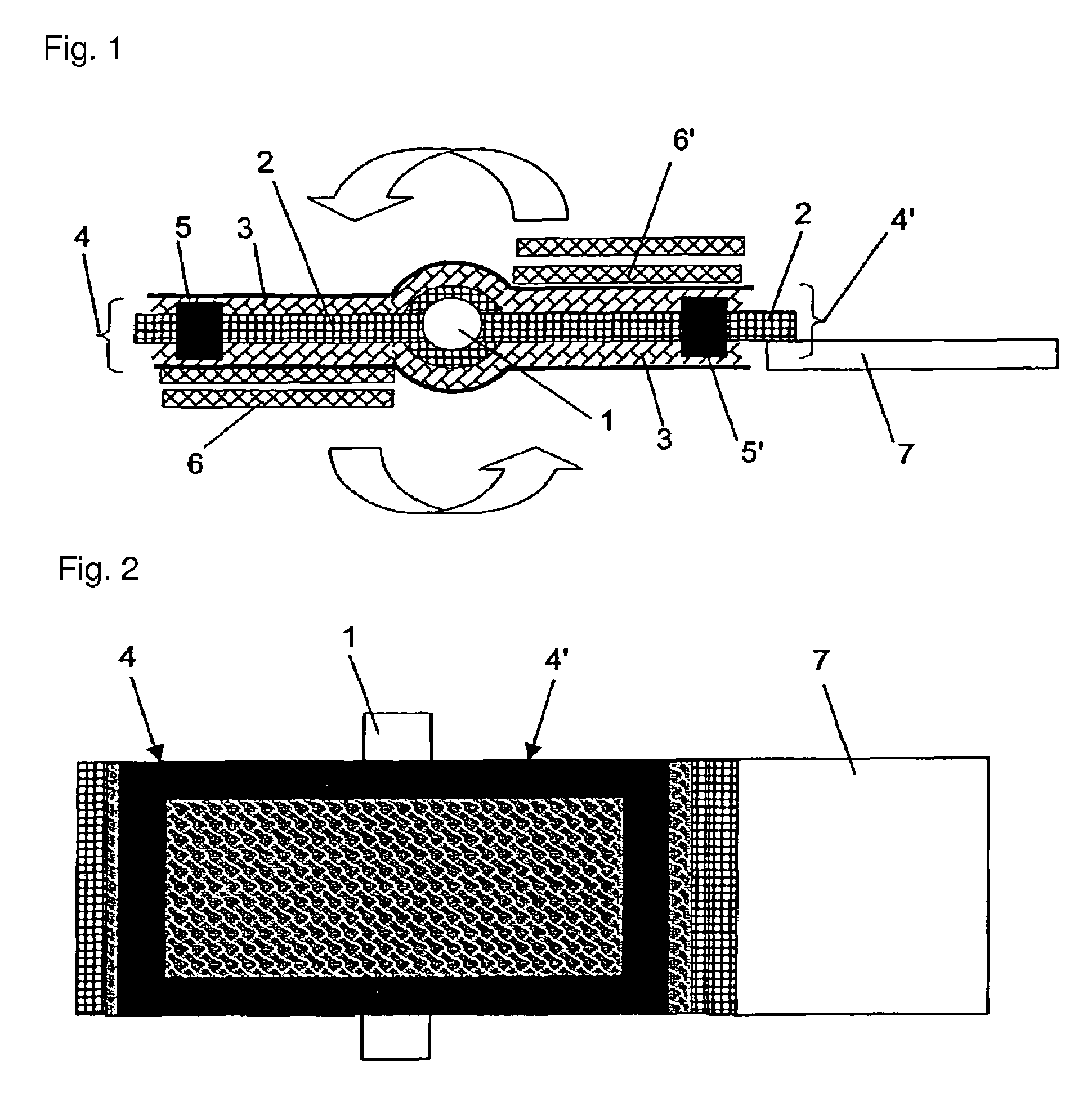
[0042]The following parts and materials were provided: an asymmetric composite separation membrane as a flat-film gas separation membrane with a thickness of 0.15 mm consisting of a polyethylene terephthalate unwoven fabric (substrate) coated by a porous polyetherimide film and then a silicone rubber separation layer having 8×10⁻⁴ cm3 (STP) / cm2·sec·cmHg of an oxygen gas permeation rate at 25° C. and 1.8 of a permeation rate ratio of oxygen to nitrogen as an indicator of separation performance; a preformed polyethylene mesh with a thickness of 0.5 mm (one sheet) as a feed-side spacer; a preformed polyethylene terephthalate mesh with a thickness of 0.5 mm as a permeate-side spacer; an ABS resin cylinder as a core tube with a length of 298 mm and an outer diameter of 17.2 mm having a hollow section inside with an inner diameter of 9.5 mm whose one end was sealed and another end was opened, and having 12 holes with inner diameter of 2.85 mm that communicate the hollow section to the o...

example 1

[0045]Oxygen-rich air was separated and recovered as described in Reference Example 1, except that a preformed polyethylene mesh with a thickness of 1.5 mm was used as a feed-side spacer. The results are shown in Table 1. A thickness ratio of the permeate-side spacer to the feed-side spacer was 1:3, and an oxygen concentration in the recovered gas was 24%. That is, oxygen-rich air was efficiently obtained.

example 2

[0046]Oxygen-rich air was separated and recovered as described in Example 1, using two laminates formed by sandwiching the permeate-side spacer between the flat-film gas separation membranes (two laminates with a width of 264 mm, a length from the core tube of 325 mm and a total film length (the front and the back together) of 650 mm). The results are shown in Table 1. A thickness ratio of the permeate-side spacer to the feed-side spacer was 1:3 and two laminates were used, and an oxygen concentration in the recovered gas was 25%. That is, oxygen-rich air was obtained more efficiently than Example 1.


PUM

PropertyMeasurementUnit
Volumeaaaaaaaaaa
Volumeaaaaaaaaaa
Volumeaaaaaaaaaa

Abstract

A method for separating and recovering oxygen-rich air from the air, comprising, using a gas separation membrane module where a laminate consisting of a permeate-side spacer for forming a permeate gas channel communicated with a hollow section in a core tube for collecting and discharging a permeate gas and two flat-film gas separation membranes sandwiching the spacer and a feed-side spacer for forming a feed gas channel are spirally wound around the core tube such that the laminate and the feed-side spacer are alternately superimposed, vacuuming the hollow section of the core tube to 95 kPaA (absolute pressure) or less by vacuuming means while feeding the air into the feed gas channel by air feed means such that a maximum feed-air flow rate and a maximum static pressure divided by an effective membrane area of the gas separation membrane are 100 m3/min·m2 or less and 4000 Pa/m2 or less, respectively, to separate and recover oxygen-rich air from the hollow section of the core tube. Oxygen-rich air can be separated and recovered from the air by this method with high separation efficiency.

Description

TECHNICAL FIELD[0001]This invention relates to a method for efficiently separating and recovering oxygen-rich air from the air using a spiral type gas separation membrane module where a flat-film gas separation membrane is wound around a core tube. It also relates to a gas separation membrane module having a convenient structure which is suitable for separating and recovering oxygen-rich air from the air.BACKGROUND ART[0002]A spiral type gas separation membrane module in which a flat-film gas separation membrane is wound around a core tube generally has a configuration where a permeate-side spacer for forming a permeate gas channel is sandwiched between flat-film gas separation membranes, which are adhered to the core tube such that the permeate gas channel communicates with a hollow section in the core tube and are wound around the core tube together with a feed-side spacer for forming a feed gas channel.[0003]Such a spiral type gas separation membrane module has a simple structure...

Claims


Application Information

Patent Timeline
IPC IPC(8): B01D53/22B01D63/10
CPCB01D53/22B01D63/10B01D63/103C01B13/0251Y10S55/05B01D2313/146C01B2210/0046B01D2257/102B01D63/101B01D69/1213B01D63/082B01D63/1031B01D63/107
Inventor TANIHARA, NOZOMU
Owner UBE IND LTD
Why Eureka
Try Eureka