Hot swap controller with zero loaded charge pump

a charge pump and controller technology, applied in pulse manipulation, pulse technique, instruments, etc., can solve the problems of affecting the circuit and/or the system, affecting the accuracy of so as to save the charge pump current, save the die area and design time, and preserve the load current limiting accuracy

Inactive Publication Date: 2010-03-23
SEMICON COMPONENTS IND LLC
View PDF9 Cites 2 Cited by
  • Summary
  • Abstract
  • Description
  • Claims
  • Application Information

AI Technical Summary

Benefits of technology

[0012]The present invention provides an output current limiting circuit that includes a small charge pump that saves on die area and design time. Since, the current from the charge pump is small, a higher charge pump voltage may be used which translates to a lower RDSon (an “on” FET resistance) for the same die area of a pass FET. In addition, an accurate current sense scheme is implemented that preserves load current limiting accuracy, saves current from the charge pump; and does not use a series sense resistor—which preserves circuit dynamic range and does not increase circuit “on” (RDSon) impedance.
[0013]In one embodiment, the present invention, compared to prior art, draws less current from Vcc, has a lower RDSon impedance uses higher voltages, and lower currents that consume less die area and are simpler designs.

Problems solved by technology

This was necessary since the random making and breaking of contacts as a circuit board or module was being inserted or removed from a connector could harm the circuits and / or the system.
However, the need to disconnect and later re-connect power is onerous, especially where entire systems may have to be powered down, possibly in set sequences, and later powering up, possibly in set sequences, and re-establishing conditions may take too much time.
Moreover, any errors in powering down or up could create high currents and power glitches that may harm the circuits.
However, these hot swapping circuits take up valuable space in such systems and often must be located externally with respect to the system they are protecting.
The use of a series sense resistor limits the voltage dynamic range of the circuit during normal operations, dissipates power and increases the impedance of the circuit.
It suffers from similar limitations as does the Bezzi patent.
Prior art circuits consume too much die area and power while exhibiting a high “on” impedance (RDSon) of a pass FET and the series sense resistor.

Method used


Image

  • Hot swap controller with zero loaded charge pump
  • Hot swap controller with zero loaded charge pump

Examples


Embodiment Construction

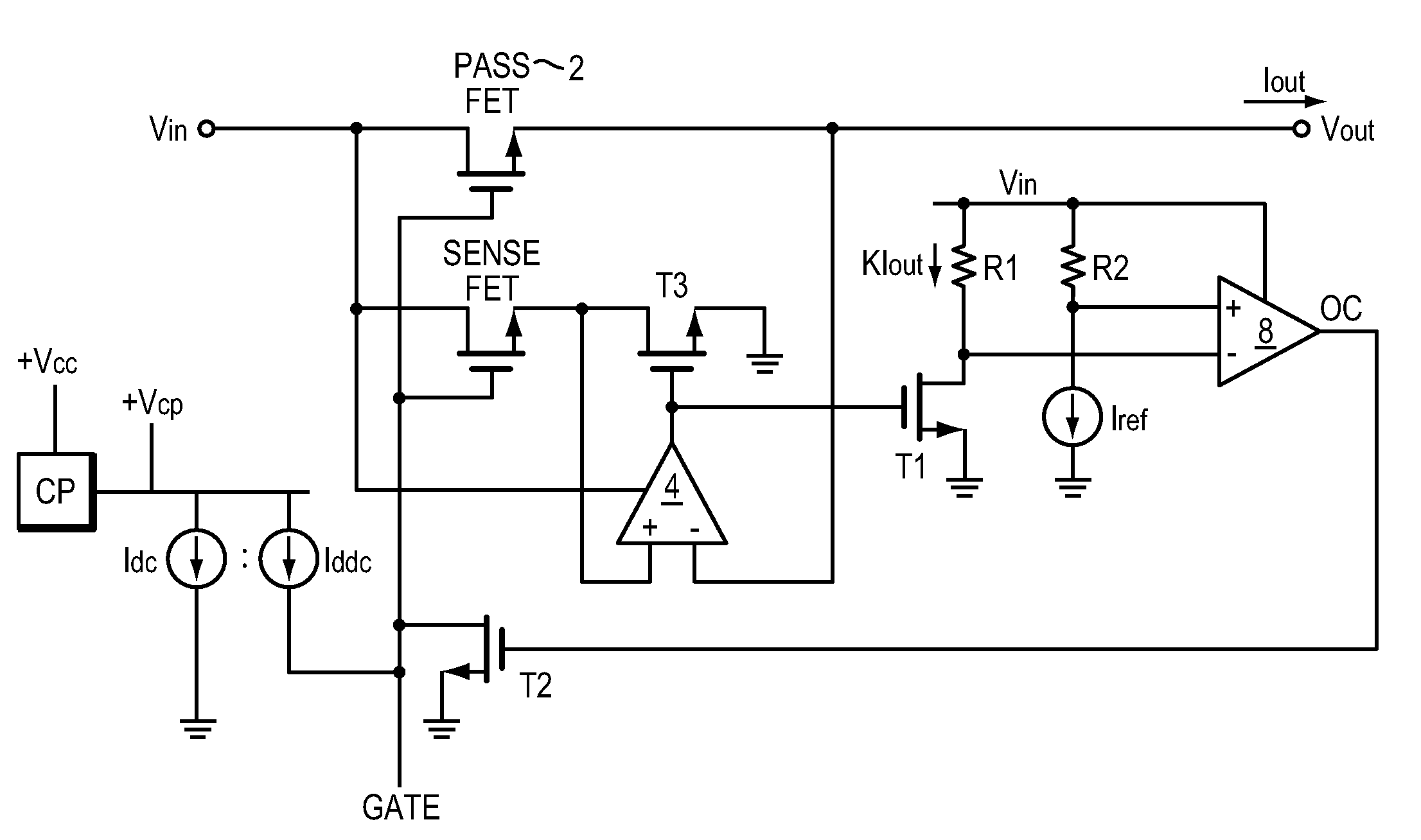
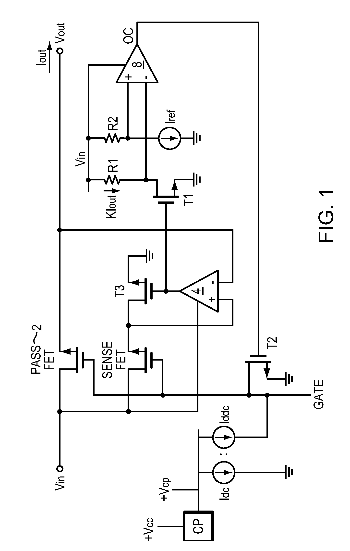
[0023]FIG. 1 illustrates one embodiment of the present invention. Here a pass FET 2 is placed between Vin and Vout and controls the Iout current provided to downstream electronics (not shown).

[0024]Vin, rather than Vcp, powers an accurate current sense circuit that indirectly senses current through the pass FET 2 and limits that current when a designed limit is reached. During normal operations, virtually no current is taken from Vcp as described below.

[0025]During typical operation, when there is no over current condition, and as mentioned above, a charge pump CP provides a voltage Vcp from which a current Idc is drawn. That current is mirrored producing Iddc that drives the capacitance (not shown) associated with the GATE. The GATE is driven up to near Vcp, whereupon it ceases to act as a current source. The current source Idc will continue to operate drawing current from Vcp, but Idc can be made small consistent with noise and leakage.

[0026]Still considering typical operation, th...


PUM


Abstract

The present invention includes a pass transistor that limits current drawn from a circuit without using a series resistor and while drawing minimal current from an external supply. A current mirror of the output current is formed and compared to a reference current. When the output current increases, the mirror current increases proportionally, and when a threshold is crossed, the pass transistor is turned off. The pass transistor is biased from a charge pump that provides a voltage, a current from which a current mirror is drawn that controls the pass transistor.

Description

RELATED APPLICATIONS[0001]The present application is related to and claims the benefit of the filing date of a provisional application Ser. No. 61 / 043,920, filed Apr. 10, 2008, and of common title, inventorship and ownership as the present application. The provisional application is incorporated herein by reference.[0002]This application is also related to another application, entitled “Technique for Combining Inrush Current Limiting and Short Circuit Current Limiting,” filed on Jun. 3, 2008 and assigned Ser. No. 12 / 132,286 which is of common inventorship and ownership as the present application, and which application is incorporated herein by reference.BACKGROUND OF THE INVENTION[0003]1. Field of the Invention[0004]The present invention relates to “hot swapping” controllers and more particularly for hot swapping while drawing about zero current from an onboard charge pump. “Hot swapping” refers to inserting and removing a circuit into or out of a computer system, without removing o...

Claims


Application Information

Patent Timeline
Patent Type & Authority Patents(United States)
IPC IPC(8): H03K5/08
CPCH03K17/0822H02H9/004
Inventor GARRETT, JAMES
Owner SEMICON COMPONENTS IND LLC
Why Eureka
Try Eureka