
Balanced acoustic wave filter

a filter device and acoustic wave technology, applied in the direction of impedence networks, electrical devices, piezoelectric/electrostrictive/magnetostrictive devices, etc., can solve the problems of unbalanced signals of antenna inputs and outputs, component having a function of unbalanced-to-balanced conversion, and the need to dispose of surface acoustic wave filters, so as to improve the balance of signals output from balanced terminals, out of band attenu

Active Publication Date: 2010-03-23
MURATA MFG CO LTD
View PDF19 Cites 10 Cited by
  • Summary
  • Abstract
  • Description
  • Claims
  • Application Information

AI Technical Summary

Benefits of technology

The present invention provides an acoustic wave filter device with a balanced-to-unbalanced conversion function and an impedance conversion function between balanced and unbalanced terminals. The device includes first and second acoustic wave filter sections each with at least three IDTs. The first and second sections have a phase difference of an output signal relative to an input signal of 180 degrees. The device also includes a third and fourth acoustic wave filter section with a phase difference of 180 degrees. The third and fourth sections are connected to a unbalanced terminal. The device can provide improved performance and reliability in filtering acoustic waves.

Problems solved by technology

In such a case, an antenna inputs and outputs unbalanced signals.
Thus, a component having a function of unbalanced-to-balanced conversion must be disposed between the antenna and the differential amplifier.
That is, the surface acoustic wave filter device 501 disclosed in Japanese Unexamined Patent Application Publication No. 2002-290203 does not provide a sufficient a sufficient impedance conversion function.

Method used


Image

  • Balanced acoustic wave filter
  • Balanced acoustic wave filter
  • Balanced acoustic wave filter

Examples


Embodiment Construction

[0054]Preferred embodiments of the present invention will now be described with reference to the drawings.

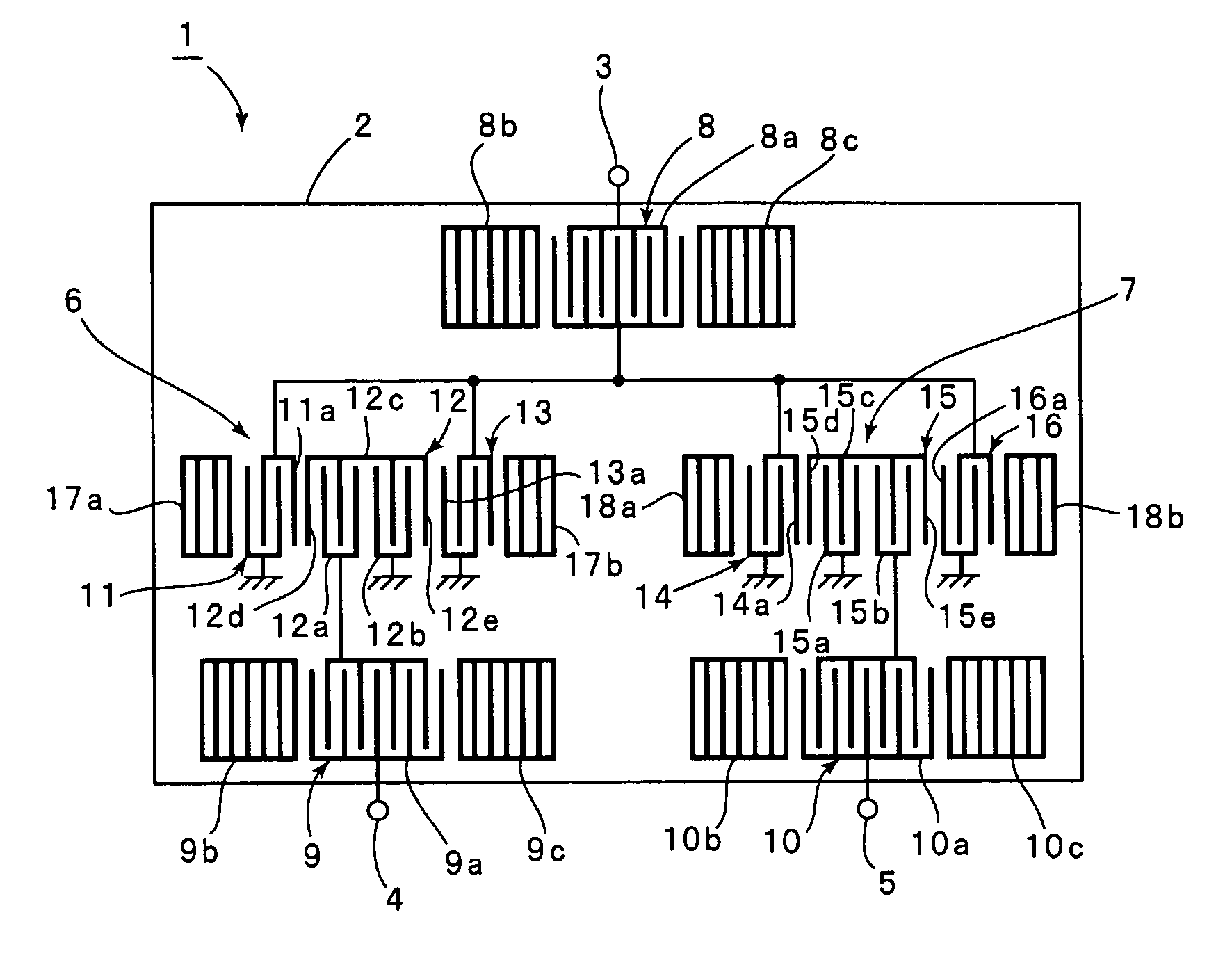
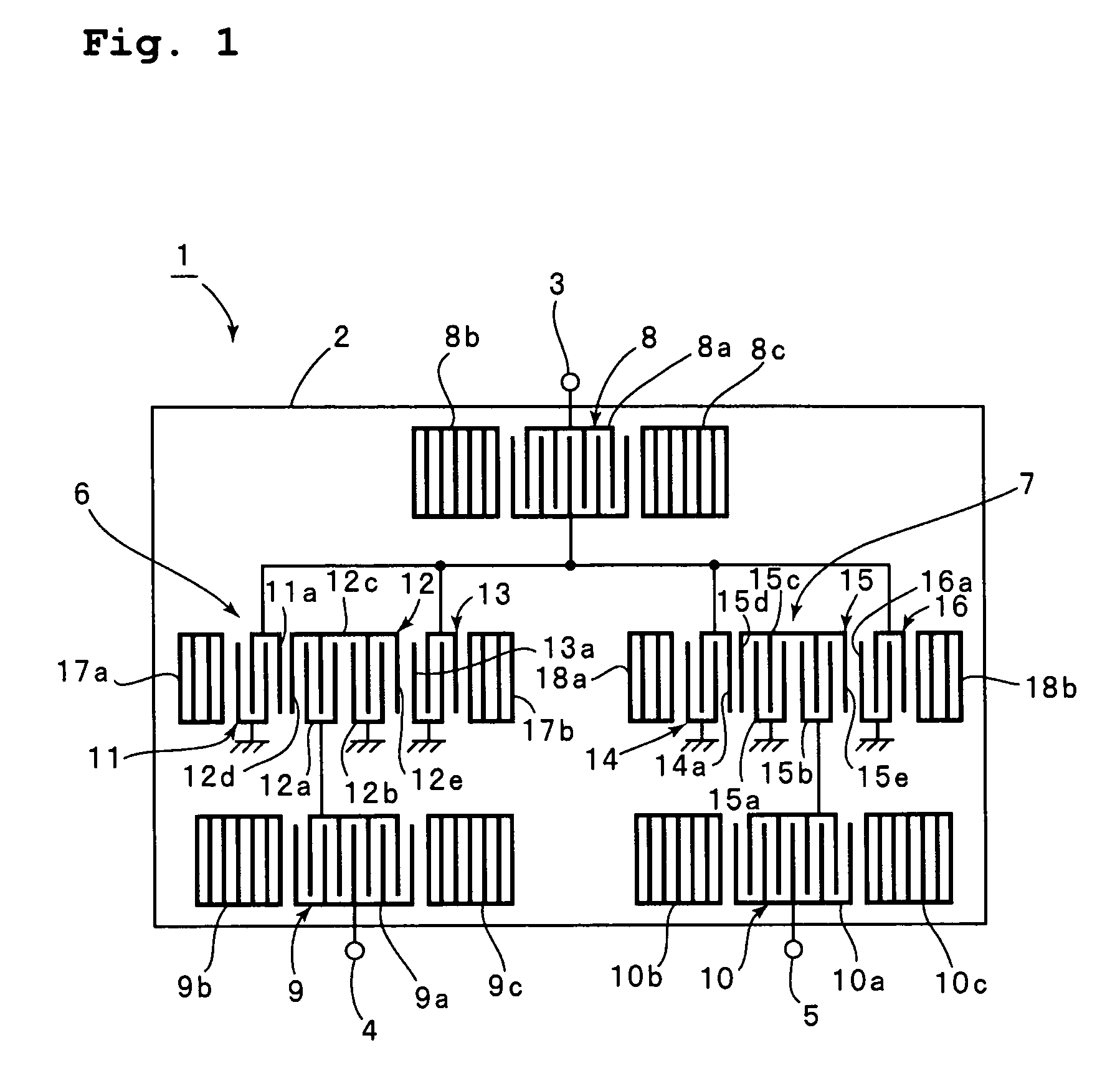
[0055]FIG. 1 is a schematic plan view of a surface acoustic wave filter device according to a preferred embodiment of the present invention. This preferred embodiment relates to a surface acoustic wave filter device having a first surface acoustic wave filter section and a second surface acoustic wave filter section each including three IDTs defined by longitudinally coupled resonators.

[0056]A surface acoustic wave filter device 1 includes a piezoelectric substrate 2. The piezoelectric substrate 2 is composed of a piezoelectric monocrystalline material, such as LiTaO3, LiNbO3, quartz, or a piezoelectric ceramic material. The piezoelectric substrate 2 may be constructed by forming a piezoelectric thin film on a base composed of a piezoelectric material or on an insulating base.

[0057]The surface acoustic wave filter device 1 according to this preferred embodiment is a balanced sur...


PUM


Abstract

In an acoustic wave filter device, first and second surface acoustic wave filter sections implemented by longitudinally coupled resonators are arranged on a piezoelectric substrate. The first and second surface acoustic wave filter sections include first to third interdigital transducers and fourth to sixth interdigital transducers, respectively, arranged in a direction of propagation of surface waves. The first, third, fourth, and sixth interdigital transducers are connected to an unbalanced terminal. The second and fifth interdigital transducers are connected to first and second balanced terminals, respectively. Each of the second and fifth interdigital transducers has first and second interdigital transducer segments divided in the direction of propagation of acoustic waves. The first and second interdigital transducer segments are connected in series with each other.

Description

BACKGROUND OF THE INVENTION[0001]1. Field of the Invention[0002]The present invention relates to balanced acoustic wave filter devices that use acoustic waves, such as surface acoustic waves or boundary acoustic waves. More specifically, the present invention relates to a balanced acoustic wave filter device having a balanced-to-unbalanced conversion function using a plurality of acoustic wave filter elements defined by longitudinally coupled resonators.[0003]2. Description of the Related Art[0004]Surface acoustic wave filters are often connected as band pass filters between antennas and differential amplifiers in mobile communication devices. In such a case, an antenna inputs and outputs unbalanced signals. On the other hand, a differential amplifier inputs and outputs balanced signals. Thus, a component having a function of unbalanced-to-balanced conversion must be disposed between the antenna and the differential amplifier. Thus, when a surface acoustic wave filter having a balan...

Claims


Application Information

Patent Timeline
Patent Type & Authority Patents(United States)
IPC IPC(8): H03H9/00H03H9/64H03H9/68
CPCH03H9/0071H03H9/0085H03H9/02748H03H9/14588
Inventor SHIBAHARA, TERUHISA
Owner MURATA MFG CO LTD
Learn More