System and method for measuring phase and power variance

a weather radar and power variance technology, applied in the field of system and method for measuring phase and power variance in weather radar systems, can solve the problems of signal phase and power change, loss of signal power prior to transmission, signal loss in coupling,

Inactive Publication Date: 2010-03-23
ENTERPRISE ELECTRONICS CORP
View PDF43 Cites 22 Cited by
  • Summary
  • Abstract
  • Description
  • Claims
  • Application Information

AI Technical Summary

Problems solved by technology

Components in a weather radar system may introduce delays in the signal (thus shifting the phase of the signal) and may also lose power from the signal prior to transmission.
For example, as the signal is passed across rotary couplers in the transmission path to the antenna, some of the signal may be lost in the coupling, and may be delayed so that the phase and power of the signal changes after it passes through the coupling.
However, in a dual channel weather system, a change in phase of the signal on one of the channels relative to the signal of the other channel introduces additional error because the analysis of a dual channel weather system includes analysis of the two received signals relative to each other.
Thus, any change in phase due to delays within the system may effect the analysis of the signals.
Moreover, any delays in the system or loss in signal power also effects the range of the signal.
Thus, signal delays and power loss may limit the range.

Method used


Image

  • System and method for measuring phase and power variance
  • System and method for measuring phase and power variance
  • System and method for measuring phase and power variance

Examples


Embodiment Construction

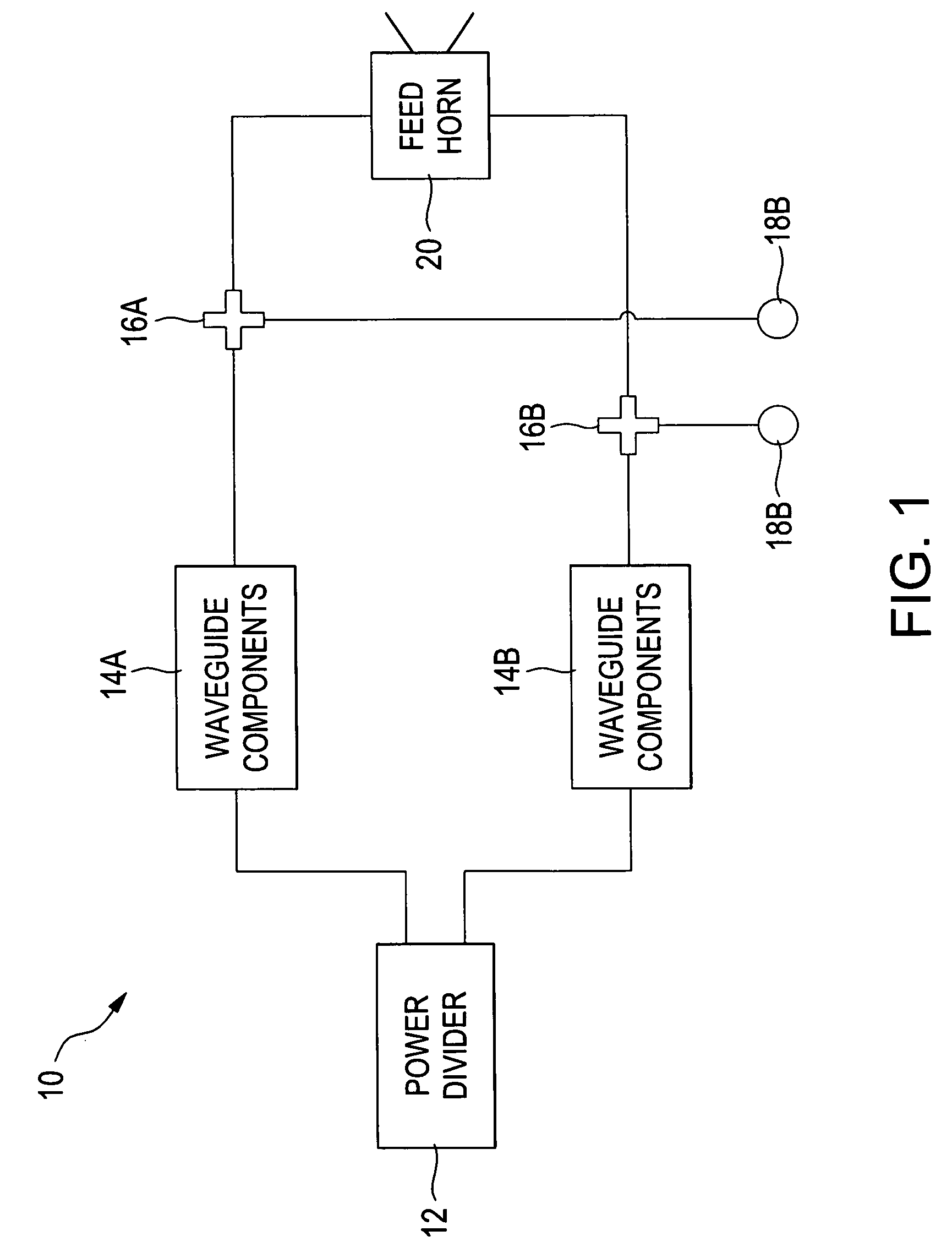
[0011]Turning now to the drawing figures, FIG. 1 is a block diagram of an embodiment of a weather radar system 10 configured with a single transmitter. The weather radar system 10 includes a power divider 12, waveguide components 14A and 14B, couplers 16A and 16B, sampling ports 18A and 18B, and a feed horn 20. The power divider 12 passes a horizontal signal and a vertical signal through the waveguide components 14A and 14B to a feed horn 20. The couplers 16A and 16B sample the horizontal and vertical signals after the signals have been passed through the waveguide components 14A and 14B.

[0012]The power divider 12 receives a high power RF signal. In one embodiment, the high power RF signal is generated from a stable local oscillator generating a stable local oscillator signal. The stable local oscillator signal is amplified in a RF tube and passed to the power divider 12. The power divider 12 may be a four port ISO terminated divider. The divider 12 may provide 20 dB of isolation fr...


PUM


Abstract

A device and method for measuring phase and power shifts in a simultaneous dual polarization radar system comprises an access port, a quadrature mixer, and a power detector. The access port is configured to couple to the simultaneous dual polarization radar system near the antenna of the simultaneous dual polarization radar system. The quadrature mixer is configured to mix a first signal from a first polarization and a second signal from a second polarization. The first signal and the second signal are sampled through the access port. The first power detector is configured to measure the power level of the first signal.

Description

FIELD OF THE INVENTION[0001]The present invention relates generally to a system and method for measuring phase and power variance in a weather radar system. More particularly, the present invention relates to a system and method for measuring the phase and power variance in the transmission signal between horizontal and vertical channels prior to transmission.BACKGROUND OF THE INVENTION[0002]In a typical dual channel weather radar system, a transmission signal is generated in an amplifier or a power oscillator, then passed through waveguides, rotary couplers and possibly transmitters and power dividers before being transmitted from an orthogonal feedhorn and antenna into the atmosphere. When a reflected signal is received, the reflected signal is compared to the signal generated by the amplifier or oscillator to determine weather conditions. The power and phase of the signal, relative to the transmitted signal, are important in determining the weather characteristics. Thus, having a...

Claims


Application Information

Patent Timeline
Patent Type & Authority Patents(United States)
IPC IPC(8): G01S7/40G01S7/03G01S7/285G01S13/00G01S13/95
CPCG01S7/025G01S7/03G01S13/87G01S13/95G01S2007/2886G01S7/2886Y02A90/10
Inventor STAGLIANO, JR., JAMES J.ALFORD, JAMES LARRYHELVIN, JAMES ROGERSNELSON, DEAN A.
Owner ENTERPRISE ELECTRONICS CORP
Why Eureka
Try Eureka