
Fiber aided wireless network architecture

a wireless network and fiber technology, applied in the field of fiber aided wireless network architecture, can solve the problems of limiting mobile communications to data rates that are lower, infrastructures that do not support mobility, etc., and achieve the effect of power efficiency and quantization error balan

Inactive Publication Date: 2010-03-23
MASSACHUSETTS INST OF TECH
View PDF10 Cites 21 Cited by
  • Summary
  • Abstract
  • Description
  • Claims
  • Application Information

AI Technical Summary

Benefits of technology

This approach enables high-speed mobile connectivity by leveraging optical fiber infrastructure, reducing interference and increasing data rates while maintaining low complexity and adaptability to variable conditions.

Problems solved by technology

However, such infrastructures do not support mobility.
However, limited available spectrum and interference effects limit mobile communications to data rates lower than data rates supported by wireline or fiber optic infrastructures.

Method used


Image

  • Fiber aided wireless network architecture
  • Fiber aided wireless network architecture
  • Fiber aided wireless network architecture

Examples


Embodiment Construction

[0022]A description of example embodiments of the invention follows.

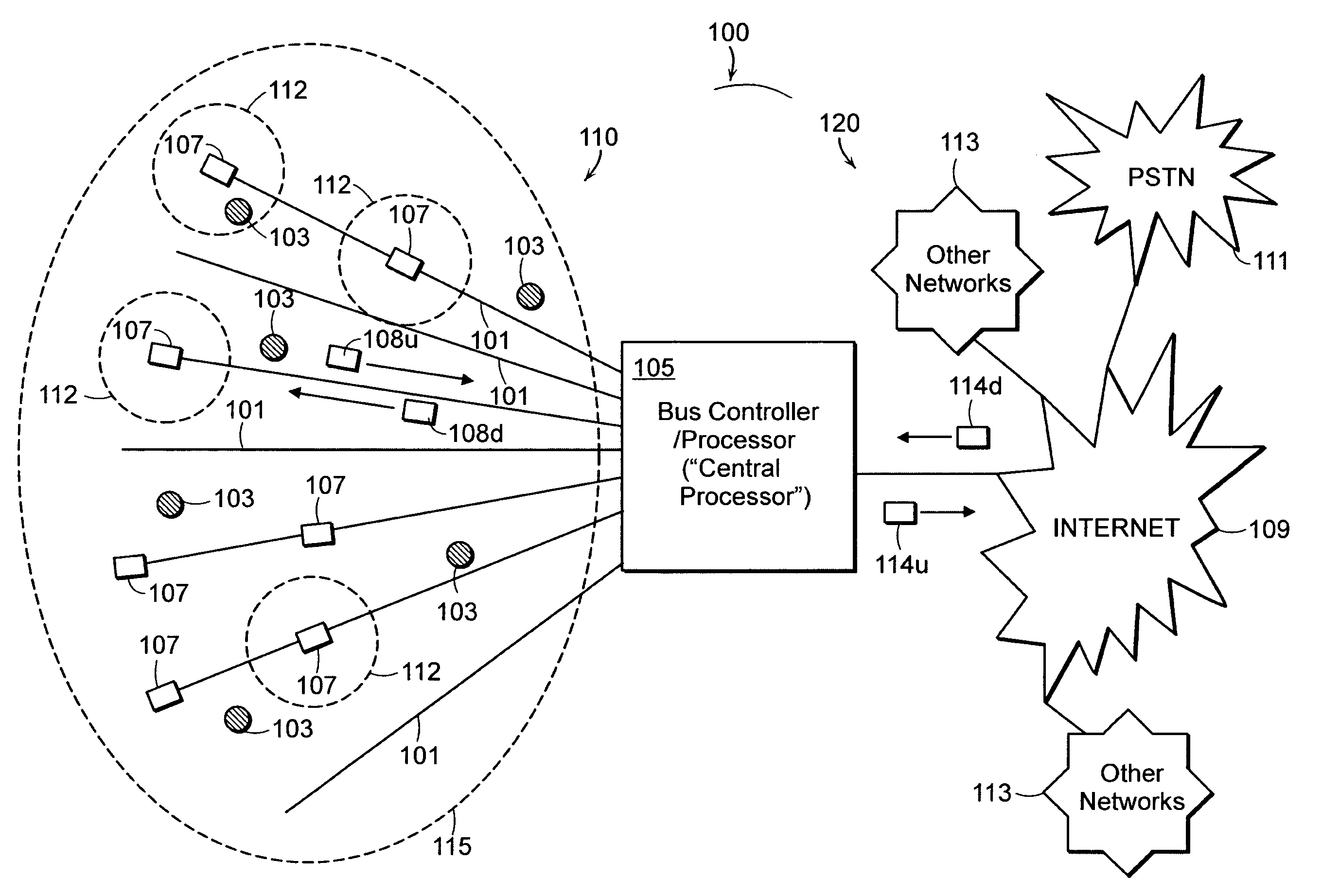
[0023]FIG. 1A illustrates an example embodiment of the present invention having a fiber aided wireless network architecture (FAWNA), which supports mobile connectivity with high-speed by leveraging speed of an optical network infrastructure. A communications network 100 includes a FAWNA system 110 employing optical fibers 101, which are passed through various wireless zones 112. A wireless network coverage area 115 may be divided into zones 112 such that the optical fibers 101 pass through each zone 112 to support the mobile connectivity.

[0024]Connected to one end of the fibers 101 is a bus controller / processor (“central processor”) 105, which coordinates use of the fibers 101 as well as connectivity to other networks 120 (“the outside world”). As shown in FIG. 1, the bus controller / processor 105 may be connected to traditional networks 120, such as the Internet 109, a public switched telephone network (PSTN) 111, o...


PUM


Abstract

A FAWNA that allows high-speed mobile connectivity by leveraging the speed of optical networks. Specifically, SIMO FAWNA, which comprises a SIMO wireless channel interfaced with a fiber channel through wireless-to-optical interfaces. Received wireless signal at each interface are sampled and quantized prior to transmission. The capacity of the FAWNA approaches the capacity of the architecture exponentially with fiber capacity. It is also shown that for a given fiber capacity, there is an optimal method of operating wireless bandwidth and number of interfaces. An optimal method to divide the fiber capacity among the interfaces is shown, which ensures that each interface is allocated a rate so that noise is dominated by front end noise rather than by quantization distortion. A method is also presented in which, rather than dynamically changing rate allocation based on channel state, a less complex, fixed rate allocation may be adopted with very small loss in performance.

Description

GOVERNMENT SUPPORT[0001]This invention was made with government support awarded by The National Science Foundation (NSF) under Grant Nos. CNS-0434974 and ANI-0335256 and by the U.S. Air Force under Grant No. F49620-01-1-0365. The Government has certain rights in this invention.BACKGROUND OF THE INVENTION[0002]Wireless networks rely on ‘free spaceradio wave based technology to enable communications between devices in a limited area. Wireless networks also provide users with mobility to move around within a broad coverage area and still be connected to the network. Wireless local area networks (LAN) typically include stations wirelessly connected to access points to access a wired network.[0003]In contrast, optical communications rely on optical waveguides to transmit an optical signal between static nodes (i.e., non-mobile). An optical communications system may include a transmitter, which modulates a message onto an optical carrier wave signal, an optical waveguide (e.g., optical ...

Claims


Application Information

Patent Timeline
Patent Type & Authority Patents(United States)
IPC IPC(8): H04B10/00
CPCH04B10/25754
Inventor RAY, SIDDHARTHMEDARD, MURIELZHENG, LIZHONG
Owner MASSACHUSETTS INST OF TECH
Learn More