Pulsed high loss loop back signalling scheme

a high-loss loop and signalling technology, applied in the field of communication systems, can solve the problems of slow speed at which information on faults in the transmission system can be collated, low signal-to-noise ratio (snr) associated with the return signal, and the inability to eliminate much of the noise generated in the pin diode in the receiver, so as to reduce the non-linear effects of system components, reduce the cost, and facilitate the collection of high-quality data.

Active Publication Date: 2010-03-23
NEPTUNE SUBSEA IP LTD
View PDF6 Cites 8 Cited by
  • Summary
  • Abstract
  • Description
  • Claims
  • Application Information

AI Technical Summary

Benefits of technology

[0013]By employing a pulsed supervisory signal the present invention permits the use of relatively cheap and simple detection circuitry. Moreover, interference with counter-propagating traffic is avoided in the present invention by utilising a dedicated supervisory wavelength, thereby improving the SNR.
[0042]Thus, the present invention provides a simple cost effective technique for monitoring the performance of components such as repeaters in an optical transmission system. A sequence of short supervisory pulses is launched into the system on a dedicated wavelength and a high-loss loop-back arrangement provides a sample of each supervisory pulse returned from each repeater. Modulation of the pulses mitigates against non-linear effects in system components. Fast collection of high accuracy data with low SNR is obtained by a combination of targeted optical filtering, pulse averaging and heterodyne reception of the loopback signal portions. Simple calibration of the system can be performed during its commissioning with pulses of sufficiently high power for a good SNR.

Problems solved by technology

One problem with the techniques described in GB2268017 is the very low signal-to-noise ratio (SNR) associated with the returning signal, wherein the loopback supervisory component must be extracted from the background traffic signal and noise.
An associated problem is the slow speed at which information on faults in the transmission system can be collated.
However, using this method in a typical system means an in-service measurement time of the order of 4 hours.
Although a data cancellation scheme is employed in the system of U.S. Pat. No. 5,825,515, it is not possible to eliminate much of the noise generated in the PIN diode in the receiver.
A separate de-convolution process is required for every repeater, which is expensive when many repeaters are present in a system.

Method used


Image

  • Pulsed high loss loop back signalling scheme
  • Pulsed high loss loop back signalling scheme
  • Pulsed high loss loop back signalling scheme

Examples


Embodiment Construction

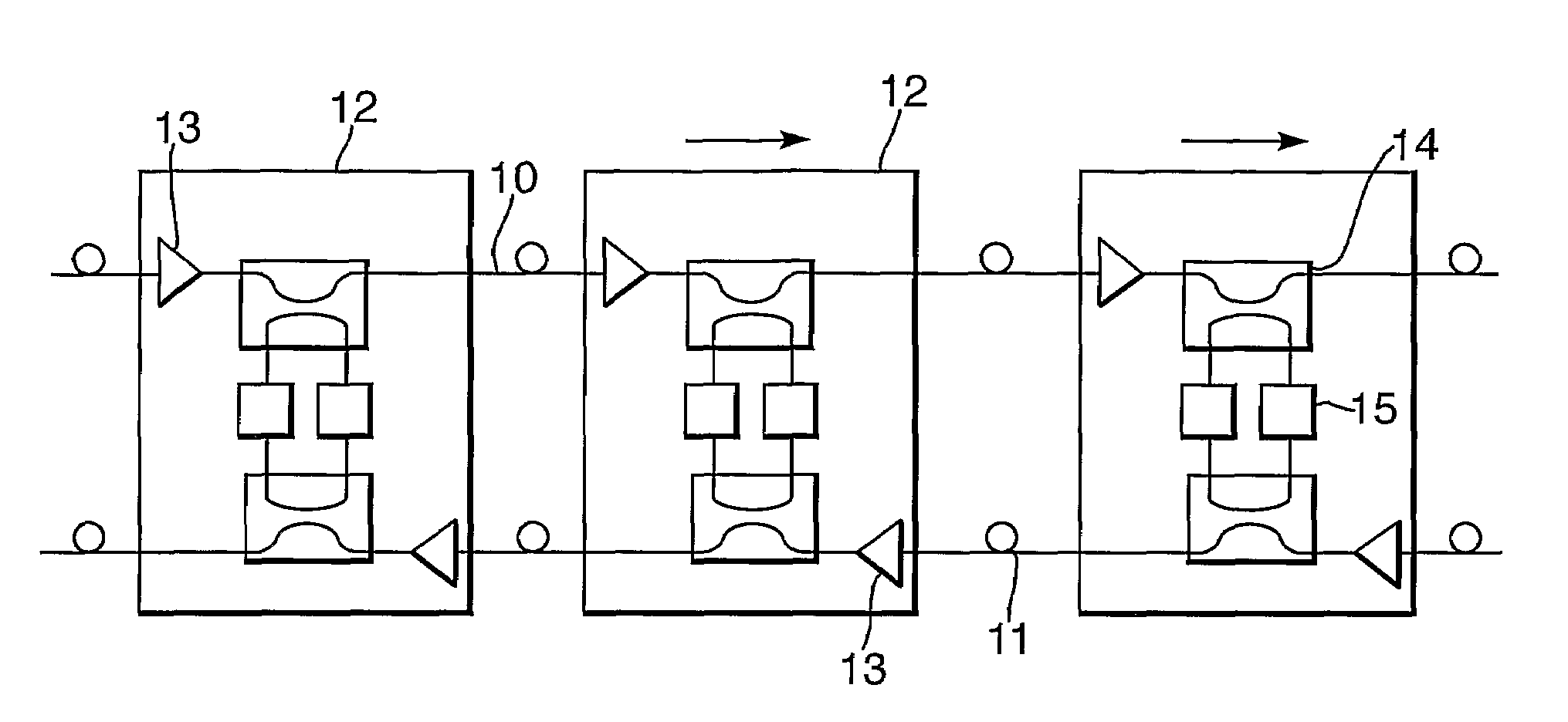
[0048]FIG. 1 is a schematic illustration of a section of a repeated optical fibre link. Three repeaters are shown in FIG. 1, but a typical long haul fibre link may include many repeaters at predetermined positions along its length in order to amplify optical signals propagating along the link.

[0049]The transmission system comprises a first optical fibre 10 which carries optical signals from a first terminal to a second terminal, as indicated by the arrows in FIG. 1. The transmission system also includes the second optical fibre 11 which carries optical signals from the second terminal to the first terminal. As optical signals travel along the optical fibres they become attenuated. Accordingly, repeaters 12 are spaced along the fibres 10 and 11 to amplify the attenuated optical signals. This amplification is accomplished by an amplifier 13 in each repeater. Each repeater has an amplifier for the first fibre 10 and an amplifier for the second fibre 11. Any suitable amplifier may be us...


PUM


Abstract

An optical transmission system comprises two optical fibers carrying optical signal traffic between two terminals, and a plurality of optical repeaters coupled to the two fibers each repeater having a permanently connected passive high loss loop back circuit between the two fibers. One terminal includes a transmitter, which launches a pulsed supervisory signal on a dedicated supervisory wavelength into one optical fiber, and a receiver, which detects a portion of the supervisory signal looped back from each repeater in order to identify the existence and location of faults in the transmission system. The pulsed supervisory signal is of sufficiently short duration such that portions of the signal returned from each repeater do not overlap with one another and interference with the counter-propagating traffic is avoided by utilizing a dedicated supervisory wavelength. Each return pulse is integrated sequentially by a single detector and processed by heterodyne reception and synchronous demodulation.

Description

FIELD OF THE INVENTION[0001]The present invention relates to communications systems and in particular to a system and method for monitoring a fibre optic transmission system.BACKGROUND TO THE INVENTION[0002]In long haul fibre optic communications systems it is important to be able to monitor the transmission properties of the system. Monitoring can be used to locate faults in the fibre or in repeaters or amplifiers. It is also desirable to be able to carry out monitoring whilst the communications system is in service. Various schemes have been proposed.[0003]GB2268017 describes a number of techniques based on the provision of a supervisory signal and a high loss loopback system in which a small proportion of the composite traffic and supervisory signal is looped back at every repeater in the transmission link. The supervisory signal may comprise a pseudo random signal, a reference signal with frequency sweep or a short pulse, and is transmitted using a sub-carrier over a single wave...

Claims


Application Information

Patent Timeline
Patent Type & Authority Patents(United States)
IPC IPC(8): H04B10/02H04B10/00H04B10/035H04B10/077H04B10/08
CPCH04B10/035H04B10/0771H04B2210/078
Inventor DESBRUSLAIS, STEVEELLISON, JOHNPOWELL, DAVID
Owner NEPTUNE SUBSEA IP LTD
Why Eureka
Try Eureka