Transition tee coupling

a technology of transition tee coupling and pipe fitting, which is applied in the direction of couplings, pipe elements, branching pipes, etc., can solve the problems of longer installation time and delay in installation of changes, and achieve the effect of fitting installation tim

a technology of transition tee coupling and pipe fitting, which is applied in the direction of couplings, pipe elements, branching pipes, etc., can solve the problems of longer installation time and delay in installation of changes, and achieve the effect of fitting installation tim

US7686346B1Inactive Publication Date: 2010-03-30ELKHART PRODS CORP

Image

  • Transition tee coupling
  • Transition tee coupling
  • Transition tee coupling

Examples


Embodiment Construction

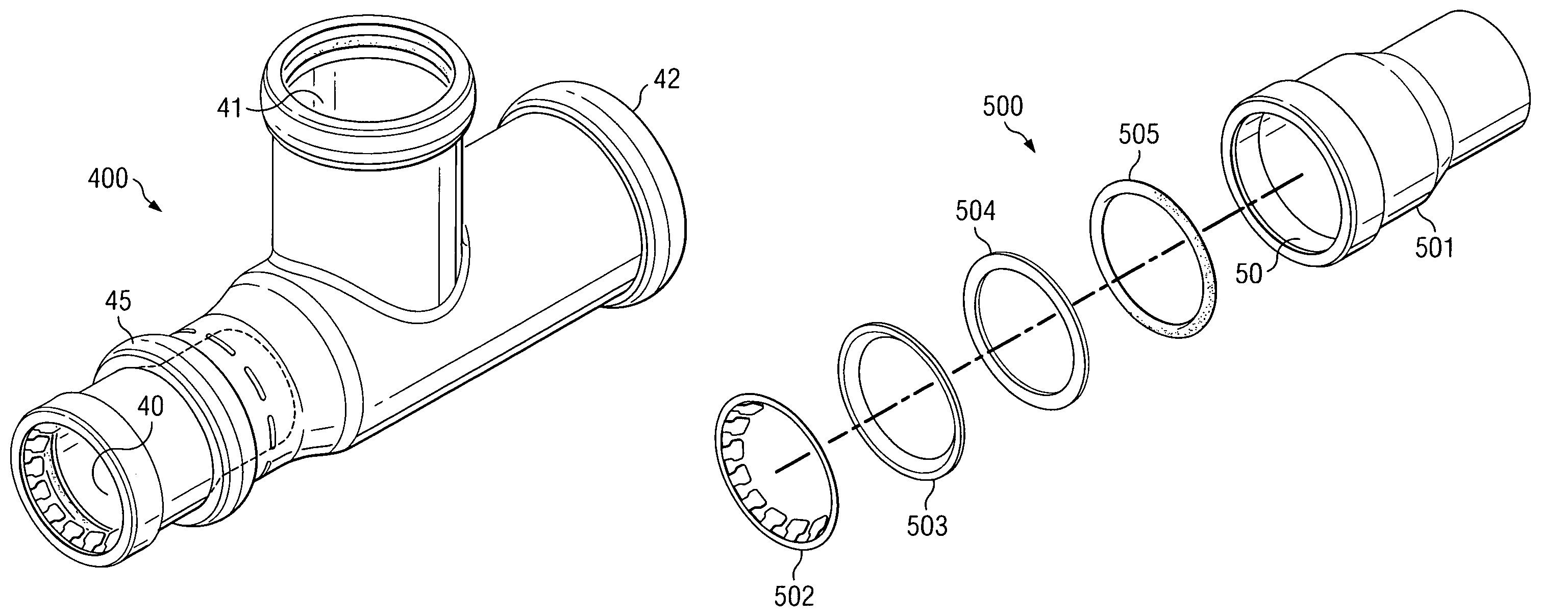
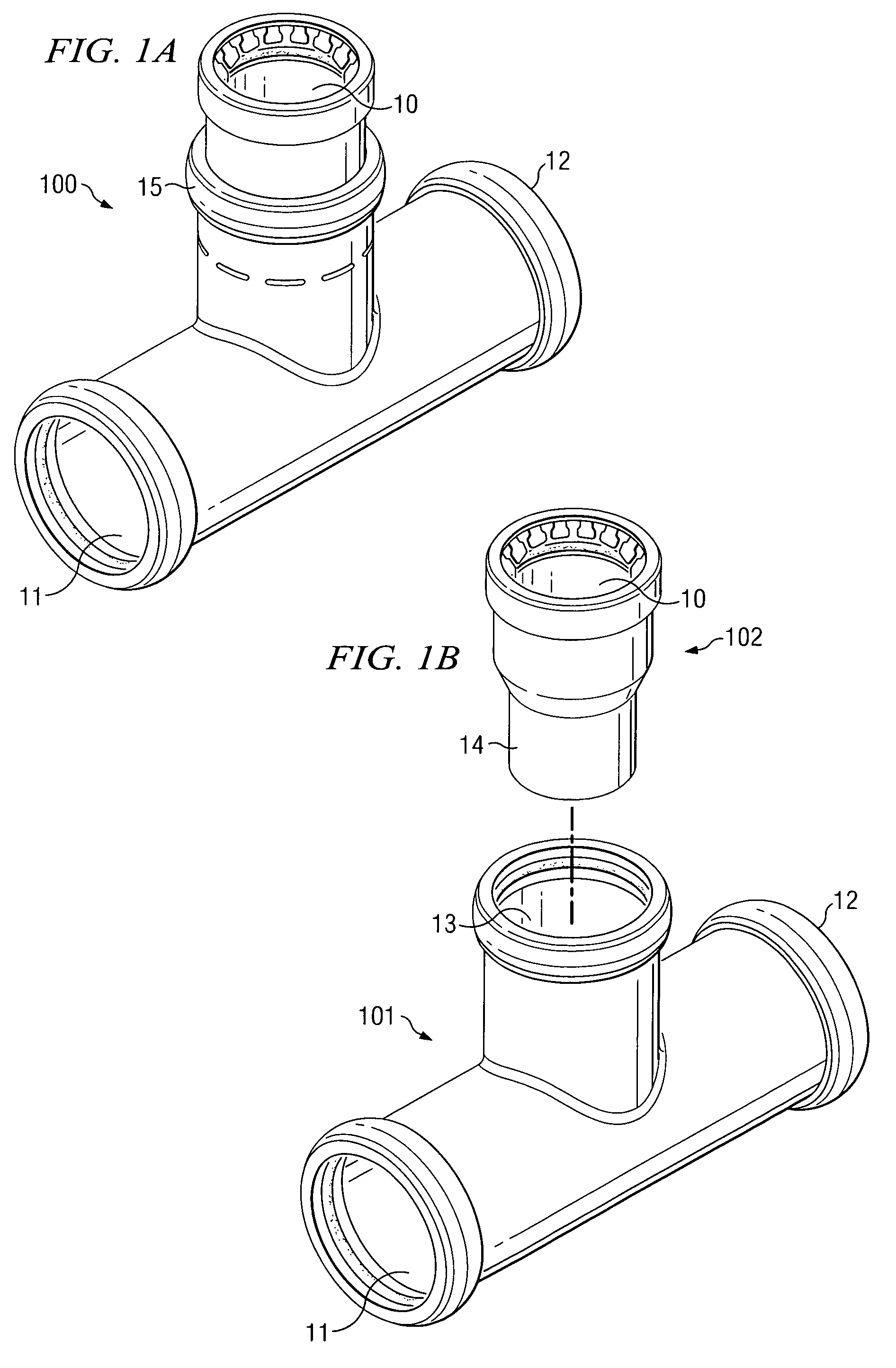
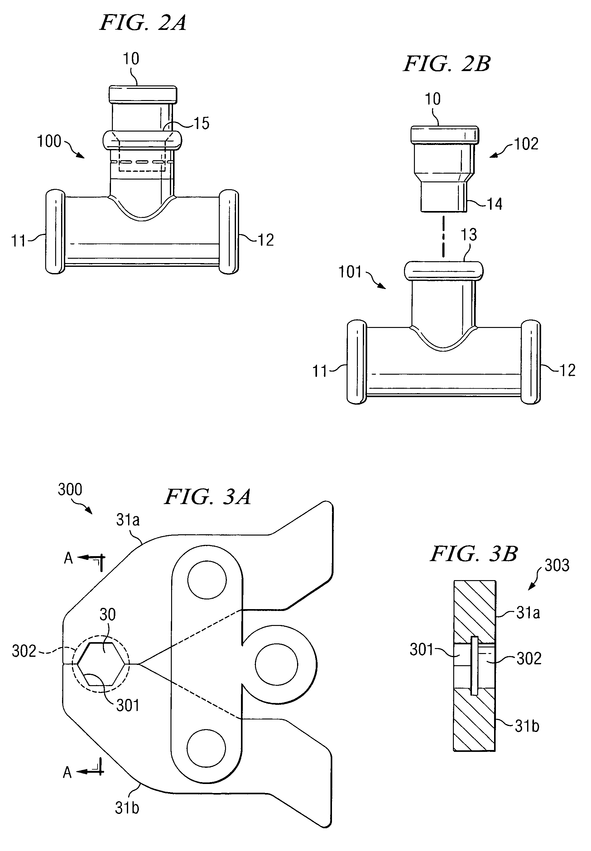
[0020]FIG. 1A is an isometric view of tee coupling 100 incorporating one embodiment of the present invention. FIG. 2A is a side view of coupling 100. Tee coupling 100 is a transition tee having outlet socket 10 with a diameter that is smaller than the diameter of end sockets 11, 12. Outlet socket 10 is a push fitting, and end sockets 11, 12 are press-fittings. FIGS. 1B and 2B illustrate the main components of transition tee coupling 100, including press-fitting tee 101 and push-fitting tailpiece 102. Press fitting tee 101 includes outlet socket 13, which is a standard press fitting that receives fit end 14 of tailpiece 102.

[0021]The invention illustrated in FIGS. 1 and 2 consists of a transition tee created using existing press-connect and push-connect fitting technology to eliminate the need to change press-connect jaw tooling during installation of a reducer tee coupling. The result is an improved reducer tee that has press-connect sockets that use a single press tool jaw, and an ...


PUM


Abstract

An improved coupling, such as a transition tee coupling, is described having press-connect fittings on the ends and a push-connect fitting on the outlet. The improved transition tee coupling is formed using a reduced-outlet tee having press-connect fittings on all three sockets. An unfinished end of a tailpiece having a push-connect fitting on the opposite end is inserted into the outlet socket of the press-connect tee. The press-connect fitting of the outlet tee is crimped using a special press tool jaw that does not damage the push fitting on the tailpiece.

Description

TECHNICAL FIELD[0001]The present invention relates in general to plumbing products and, more particularly, to tee couplings or pipe fittings having a combination of press-connection and push-connection sockets.BACKGROUND OF THE INVENTION[0002]Press copper fittings provide secure, reliable joints for plumbing connections. Specially engineered O-rings in the sockets of the fitting are tightened onto the tube or piping using a press-fit tool. A watertight seal is created by applying pressure from the press-fit tool, which tightens the O-ring onto the tube, ensuring a perfect fit.[0003]Using press fittings, plumbers can install tubing and pipes with less trouble in less time and effort than what is required when using other methods, such as soldered or threaded fittings. Press fittings allow plumbers to spend less time on site. With press fittings, plumbers create strong, long-lasting joints with significant time savings, especially on large-diameter applications. The installation proce...

Claims


Application Information

Patent Timeline
30 Mar 2010
Publication
US7686346B1
IPC
F16L41/00
CPC
F16L41/021; F16L13/142; F16L37/091
Inventors
BUCCICONE, DANA F.; JOHNSON, LARRY W.