Hydraulic tensioner
a technology of hydraulic tensioner and traction member, which is applied in the direction of mechanical equipment, belts/chains/gearrings, and adjusting devices, etc., can solve the problems of affecting the biasing force of the traction member, faulty operation of the tensioner, and lost motion, so as to prevent an undesired loss of motion and large volume
- Summary
- Abstract
- Description
- Claims
- Application Information
AI Technical Summary
Benefits of technology
Problems solved by technology
Method used
Image
Examples
first embodiment
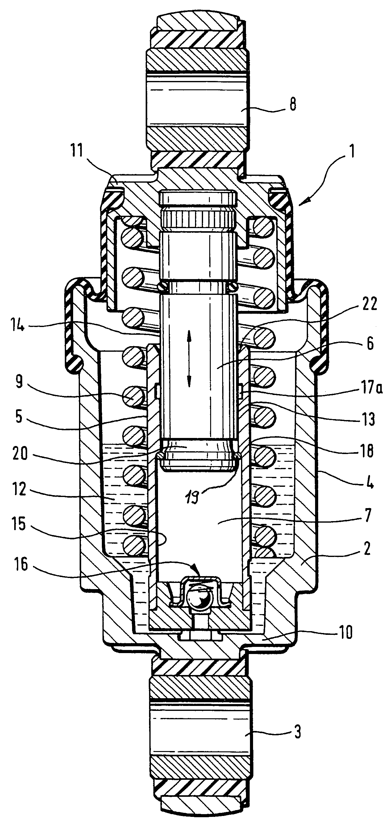
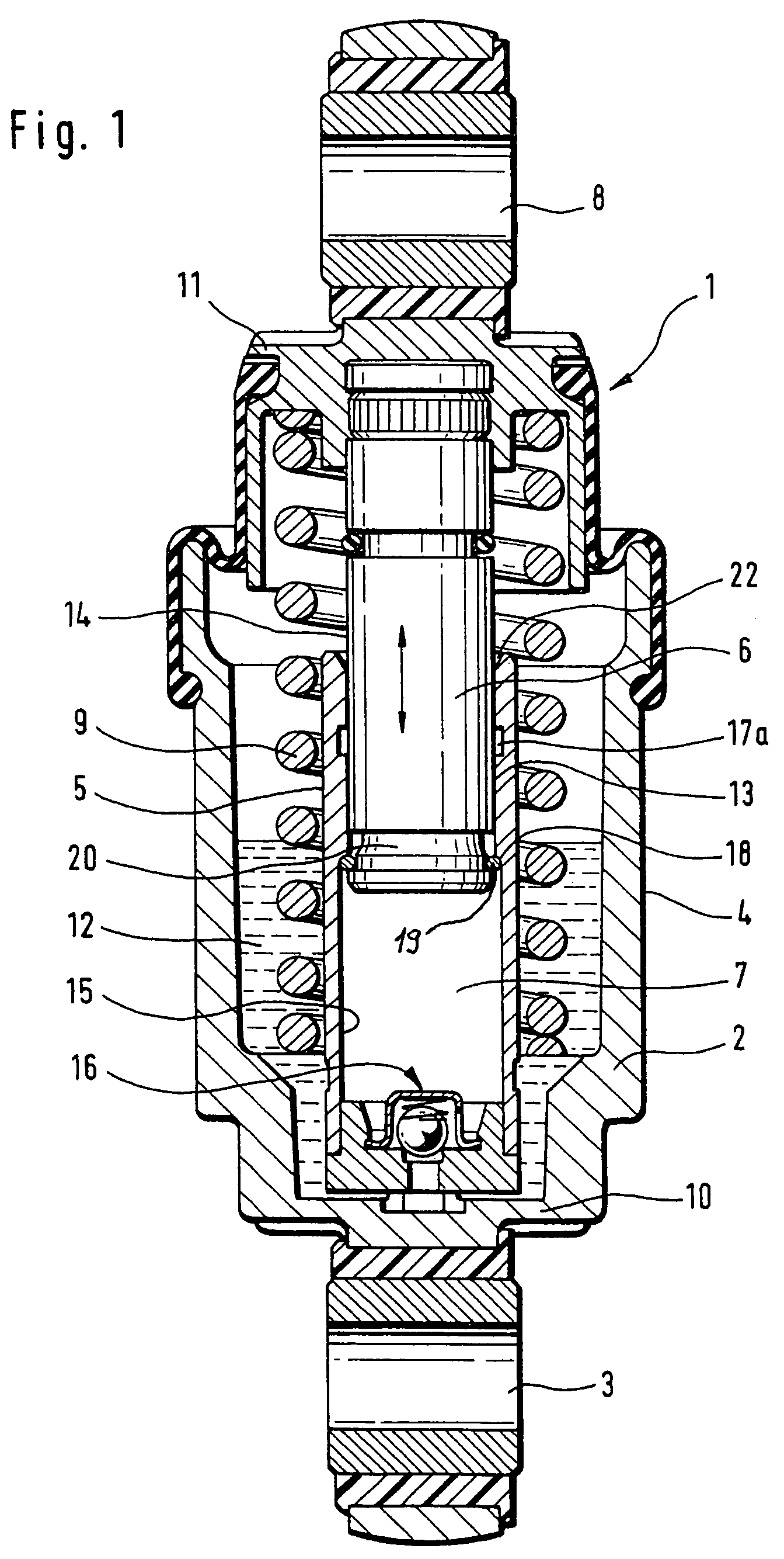
[0028]Turning now to the drawing, and in particular to FIG. 1, there is shown a longitudinal section of a hydraulic-mechanical tensioner according to the present invention, generally designated by reference numeral 1 and including a rotation-symmetric housing 2 of pot-shaped configuration. The housing 2 has one end connected to a fastening eye 3 which, for example, is swingably mounted to an internal combustion engine (not shown). Fitted centrally in the housing 2 radially inwards at a distance to an outer wall 4 of the housing 2 is a cylinder 5 which guides a piston 6 for longitudinal movement. A leakage gap 13 is defined between an outer surface area 14 of the piston 6 and an inside wall 15 of the cylinder 5. The piston 6 has one end surface to bound a pressure chamber 7 inside the cylinder 5 for hydraulic fluid, and another cylinder-distal end for connection to a fastening eye 8 which interacts directly or indirectly with a tension roller (not shown) for tensioning a traction mem...
second embodiment
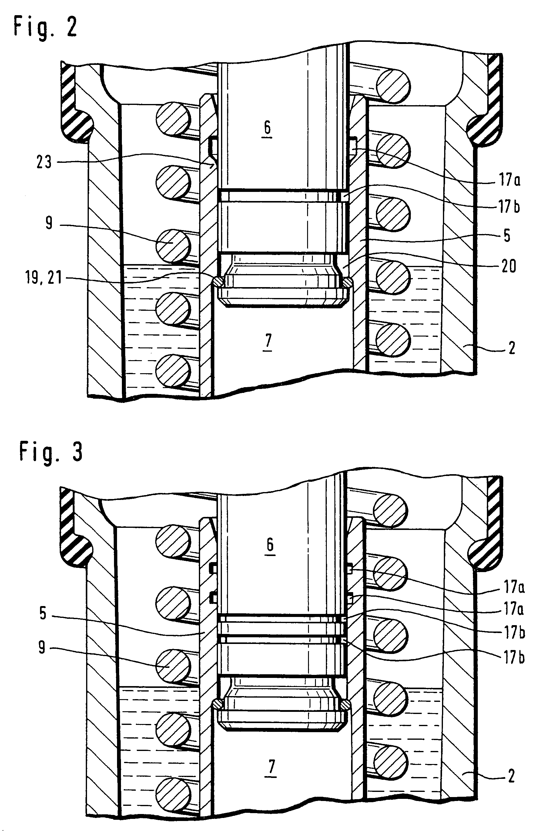
[0033]Turning now to FIG. 2, there is shown an enlarged detailed sectional view of a tensioner 1 according to the present invention. Parts corresponding with those in FIG. 1 are denoted by identical reference numerals and not explained again. The description below will center on the differences between the embodiments. In this embodiment, provision is made for a further reservoir 17b in the form of a circumferential groove in the piston 6 for hydraulic fluid. The provision of two reservoirs 17a, 17b increases the amount of hydraulic fluid in the leakage gap 13 to prevent a complete drainage, when hydraulic fluid is drawn by the underpressure into the pressure chamber 7. The reservoir 17a is configured with a slanted boundary surface which terminates in a rounded transition zone 23 to prevent the snap ring 19 from permanently snapping into the reservoir 17a, when the piston 6 is pushed into the cylinder 5.
[0034]A variation of the tensioner 1 is shown in FIG. 3 in which the reservoir ...
PUM
 Abstract
Description
Claims
Application Information
 - R&D
- Intellectual Property
- Life Sciences
- Materials
- Tech Scout
- Unparalleled Data Quality
- Higher Quality Content
- 60% Fewer Hallucinations
Browse by: Latest US Patents, China's latest patents, Technical Efficacy Thesaurus, Application Domain, Technology Topic, Popular Technical Reports.
© 2025 PatSnap. All rights reserved.Legal|Privacy policy|Modern Slavery Act Transparency Statement|Sitemap|About US| Contact US: help@patsnap.com


