Plate-link chain for a continuously variable transmission

a technology of continuous transmission and plate-link chain, which is applied in the direction of driving belts, chain elements, v-belts, etc., can solve the problems of inability to follow a long chain link again by a long link, and achieve the effect of prolonging the service life of the plate-link chain, reducing the effective pitch length, and reducing the end wear

Active Publication Date: 2010-03-30
SCHAEFFLER TECH AG & CO KG
View PDF10 Cites 5 Cited by
  • Summary
  • Abstract
  • Description
  • Claims
  • Application Information

AI Technical Summary

Benefits of technology

[0014]The plate-link chain provided according to the invention is therefore made up of a large number of rocker members and link plates. To form the plate-link chain, two different types of link plates are provided, namely a short link plate, viewed in the longitudinal direction of the plate-link chain that is being formed, and a long link plate, also viewed in that longitudinal direction, so that they differ in terms of their longitudinal extent. Projections can also be provided on individual link plates so that the projections overlap link plates that are positioned in an offset arrangement, and thus prevent lateral displacement of the link plates, i.e. in the transverse direction of the plate-link chain.
[0018]Thus that formation sequence again makes a so-called random pitch plate-link chain possible, with smoothing of the entry noise of the rocker members on the surfaces of the conical disks, but where the wear performance of the plate-link chain according to the invention is improved over the known plate-link chain. The reduction of the effective pitch length between two adjacent pairs of rocker members results in a reduction of the end wear on the rocker members, and thus to a prolongation of the service life of the plate-link chain according to the invention.
[0019]Thereby it is possible for a belt-driven conical-pulley transmission having a plate-link chain according to the invention to be employed in commercial vehicles that have significantly longer service times in a defined comparison period than passenger cars, for example, and hence can benefit from the advantage of an extended service life of the plate-link chain and thus of the belt-driven conical-pulley transmission. Since the background noise affecting the driver of such a commercial vehicle is already louder than that in the case of a passenger car, any worsening of the noise behavior of a belt-driven conical-pulley transmission having a plate-link chain according to the invention can be tolerated, since that drawback, which hardly manifests itself or does not manifest itself at all in the driving operation of the commercial vehicle, is more than compensated by the benefit of the longer service life of the transmission.

Problems solved by technology

Thus a short chain link must follow a long chain link, and the case of a long chain link being followed again by a long link is not possible.

Method used


Image

  • Plate-link chain for a continuously variable transmission
  • Plate-link chain for a continuously variable transmission
  • Plate-link chain for a continuously variable transmission

Examples


Embodiment Construction

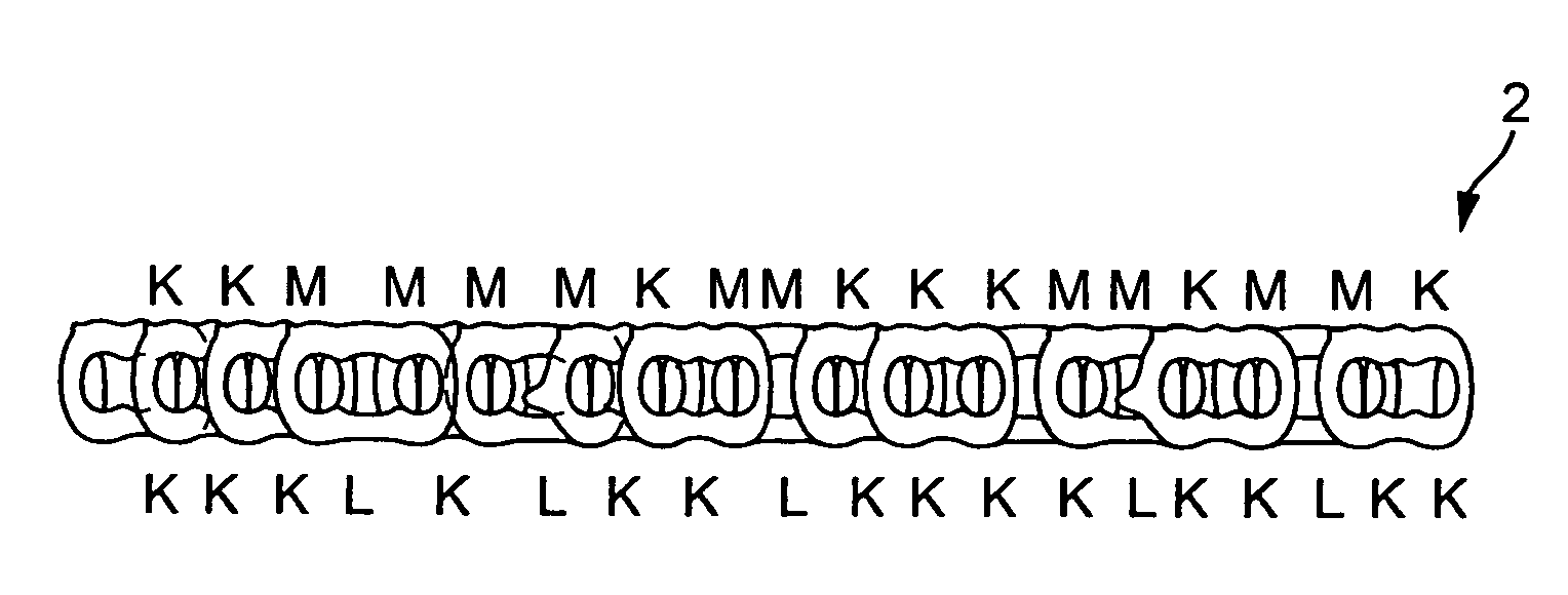
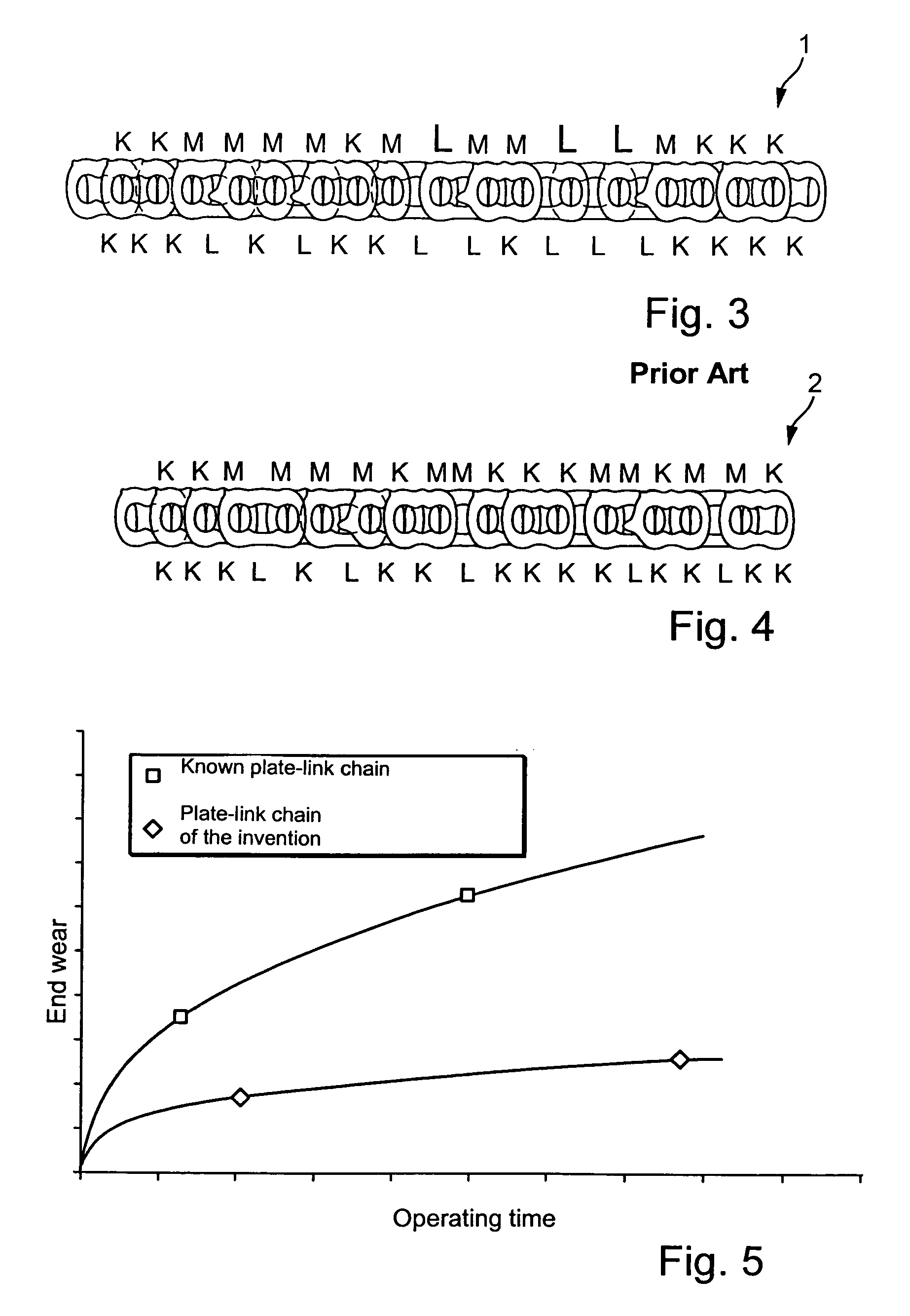
[0026]FIG. 3 of the drawings shows a side view of a segment of a known plate-link chain. K and L in the area beneath plate-link chain 1 designate the length of individual links of plate-link chain 1. K therefore designates a short link of plate-link chain 1, i.e., a link having short link plates, while L designates a long link of the plate-link chain. In the random pitch plate-link chain 1 according to FIG. 3, a long link L can follow another long link L, so that a large or long effective pitch between two adjacent pairs of rocker members results. The effective pitch is indicated in FIG. 3 of the drawing with K, M, and L above plate-link chain 1. K corresponds here to the effective pitch between two adjacent short chain links. If a short chain link is followed by a long chain link, then a pitch of medium length M occurs between the two adjacent pairs of rocker members, and if a long chain link is followed by another long chain link, then a long pitch L occurs between the two adjacen...


PUM


Abstract

A plate-link chain for a belt-driven conical-pulley transmission. The chain has a large number of link plates that are articulatingly connected with each other by rocker members, which link plates are positioned one behind the other and are offset from each other transversely relative to the longitudinal direction of the plate-link chain, and also partially overlap each other. The chain has a plurality of link plates of two different lengths in the longitudinal direction of the chain, with openings to receive the rocker members. The arrangement of the link plates in the longitudinal direction of the chain is such that a long link plate is followed by a short link plate.

Description

BACKGROUND OF THE INVENTION[0001]1. Field of the Invention[0002]The present invention relates to a plate-link chain for a belt-driven conical-pulley transmission. The chain has a large number of link plates that are articulatingly connected with each other by rocker members. The link plates are positioned one behind the other transversely to the longitudinal direction of the plate-link chain, and are offset from each other in the longitudinal direction of the chain and partially overlap each other. The chain has a plurality of link plates of two different lengths in the longitudinal direction of the chain, with openings to receive the rocker members.[0003]2. Description of the Related Art[0004]A plate-link chain of the type described herein is made up of a large number of link plates and rocker members, the rocker members also being referred to as pegs or pins, and also being known as rocker hinges.[0005]The link plates for forming such a plate-link chain are selected from two types...

Claims


Application Information

Patent Timeline
Patent Type & Authority Patents(United States)
IPC IPC(8): F16G13/04F16G13/02
CPCF16G5/18
Inventor BAUMANN, MARKUSPICHURA, MICHAEL
Owner SCHAEFFLER TECH AG & CO KG
Why Eureka
Try Eureka