Method for setting the rotational position of a femoral component

a technology for femoral components and rotational positions, applied in the field of femoral components, can solve the problems of femoral and/or tibia rotational alignment, on-bone contact, significant pain and discomfort, etc., and achieve the effect of correct rotational alignmen

Active Publication Date: 2010-03-30
HOWMEDICA OSTEONICS CORP
View PDF22 Cites 34 Cited by
  • Summary
  • Abstract
  • Description
  • Claims
  • Application Information

AI Technical Summary

Benefits of technology

[0009]The present invention helps surgeons to accomplish the correct rotational alignment by allowing the femoral trial to rotate via a radial arc created on the posterior condyles in flexion. The knee can be taken through a range of motion, and the trial will self-adjust to the correct rotation without the need to provide secondary mechanical methods to adjust or torque the knee. Gap balancing is accomplished by changing the thickness of the insert to provide the proper balance between the flexion and extension space.
[0014]While mechanical spacer blocks or positioners allow the knee rotation to be balanced by aligning the cutting guides with the tibial resection while tensioning the ligaments, however, they do not allow for a dynamic assessment to be accomplished prior to locking in femoral rotation. By using a mechanism to torque the knee about either the medial or lateral point via a mechanical device, the surgeon could over tighten the device and provide too much rotation.

Problems solved by technology

This bone-on-bone contact causes significant pain and discomfort.
One of the challenges in knee surgery is to properly balance ligament tension, especially in the medial and lateral collateral ligaments, through a full range of motion of the knee.
If one of the collateral ligaments is too lax or too tight relative to the other collateral ligament, the knee will typically be unstable, range of motion may be limited, the patella may track improperly, and the femur and / or tibia may wear unevenly, leading to arthritis and pain.
Uneven ligament tension after knee surgery will typically cause joint instability and poor patellar tracking, limited range of motion, and impaired function of the knee, as well as uneven, increased wear of the prosthetic device, which often necessitates repeat surgery.

Method used


Image

  • Method for setting the rotational position of a femoral component
  • Method for setting the rotational position of a femoral component
  • Method for setting the rotational position of a femoral component

Examples


Embodiment Construction

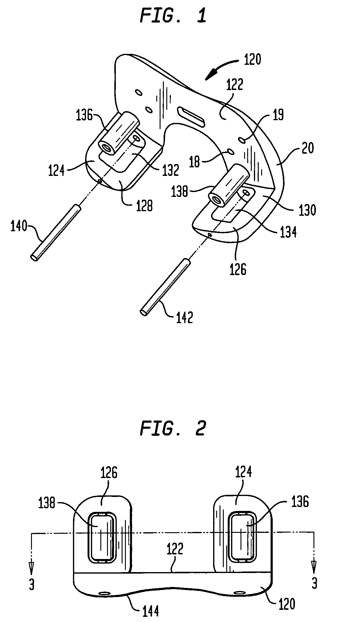
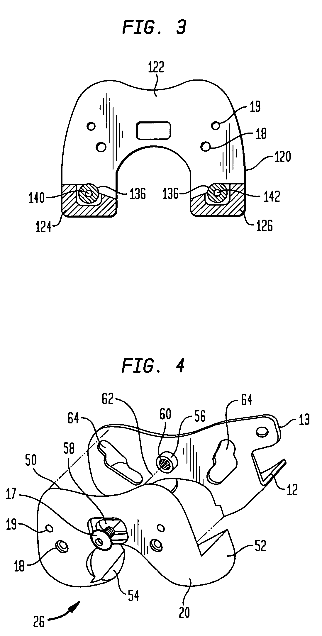
[0033]Referring to FIGS. 1-3, there is a first preferred one-piece embodiment of a femoral trial assembly generally denoted as 120. Femoral trial 120 includes a proximally facing surface 122 for contacting the resected distal surface of a femur. The femoral trial 120 has a pair of posterior condyles 124 and 126 which have curved anteriorly facing surfaces 128 and 130 respectively. The curved surfaces 128 and 130 are cylindrical surfaces each having a radius of 1.9 to 4 inches with a center located on or slightly offset from the center line of the distal femur. In the preferred embodiment a pair of recesses 132 and 134 are formed in the anterior surfaces 128 and 130 to receive roller bearings 136 and 138. Bearings 136 and 138 are held within recesses 130 and 132 by pins 140 and 142. Pins 140 and 142 provides the axes of rotation about which roller bearings 136 and 138 rotate. Surface 122 has a plurality of pin holes 19 therethrough to receive bone pins for mounting the trial on the d...


PUM


Abstract

A method for setting the internal-external rotational position of a prosthetic femoral component with respect to the tibial comprises: forming a cylindrical surface on the posterior femoral condyles. The cylindrical surface is formed about an axis extending in a proximal distal direction with respect to the femur. A template is placed on the distal femur which has a cylindrical guide surface for engaging the posterior femoral condyles. When placed against a planar resected surface of the distal femur the guide surfaces contact the cylindrically shaped posterior condyles. The template is rotated on the cylindrical guide surface as the knee joint is moved from flexion to extension until the template cylindrical guide surfaces are in a position with respect to the tibial condyle surfaces to properly balance the knee ligaments.

Description

BACKGROUND OF THE INVENTION[0001]The present invention relates generally to a femoral component having curved or radially shaped anterior surface of the posterior condyles and instruments for use in implanting the same and more particularly for instruments for use in balancing the ligaments extending between the femur and tibia.[0002]Structures that made up the knee joint include the distal femur, the proximal tibia, the patella, and the soft tissues within and surrounding the knee joint. Four ligaments are especially important in the functioning of the knee—the anterior cruciate ligament, the posterior cruciate ligament, the medial collateral ligament, and the lateral collateral ligament. In an arthritic knee, protective cartilage at the point of articulation of the femur with the tibia has been worn away to allow the femur to directly contact the tibia. This bone-on-bone contact causes significant pain and discomfort. The primary goals of a knee procedure are to replace the distal...

Claims


Application Information

Patent Timeline
Patent Type & Authority Patents(United States)
IPC IPC(8): A61B17/58A61B17/60A61F2/00
CPCA61B17/155A61B17/1764A61F2/4684A61F2002/3895A61F2/389A61F2/38
Inventor AXELSON, JR., STUART L.D'ALESSIO, II, JERRY
Owner HOWMEDICA OSTEONICS CORP
Why Eureka
Try Eureka