Method and apparatus for producing synthesis gas

a synthesis gas and gas technology, applied in the direction of gaseous fuels, combustible gas production, electrochemical generators, etc., can solve the problems of metals that are not brittle, metals that are also subject to creep at high temperatures, and ceramic supports that fail to meet the requirements of high temperature environments

Inactive Publication Date: 2010-03-30
PRAXAIR TECH INC +1
View PDF11 Cites 43 Cited by
  • Summary
  • Abstract
  • Description
  • Claims
  • Application Information

AI Technical Summary

Benefits of technology

[0015]The temperature within each of the reaction stages is controlled by providing a sufficient number of the reaction stages so that at least the final of the reaction stages operates at a temperature range of between about 900° C. and about 1100° C. and at least one of the reaction stages, located upstream of the at least final reaction stage has an operational temperature that is less than the temperature range due to the consumption of the heat in the endothermic reactions occurring within the at least one of the reaction stages. This allows the use of the high temperature alloys within the final reaction stage or stages and less expensive materials within stages located upstream of the final stage or stages. Advantageously, either the fuel streams containing the fuel can be separately metered into the combustion zones of each of the reaction stages and / or the oxygen containing streams containing the oxygen containing gas can be separately metered into the separation zones of each of the reactions stages. The metering or control of the fuel or the oxygen allows a further degree of control to be exercised over the temperature distribution within the reaction stages to allow for the degree of conversion taking place within each of the reaction stages to be maximized within temperature constraints of the materials being used in each of the stages.

Problems solved by technology

The use of oxygen transport membranes within high temperature environments is problematical because the membrane tends to degrade over time and fail.
One problem that has been found to effect longevity is the fact that over time, the ceramic support will fail by the known action of creep.
Metals while not being brittle are also subject to creep at high temperatures.
Additionally, in the pure oxygen and highly oxidative environment in which oxygen ion transport elements operate, metals also suffer failure due to oxidation.
The problem with the use of such materials within reactors is that they are very expensive.

Method used


Image

  • Method and apparatus for producing synthesis gas
  • Method and apparatus for producing synthesis gas
  • Method and apparatus for producing synthesis gas

Examples


Embodiment Construction

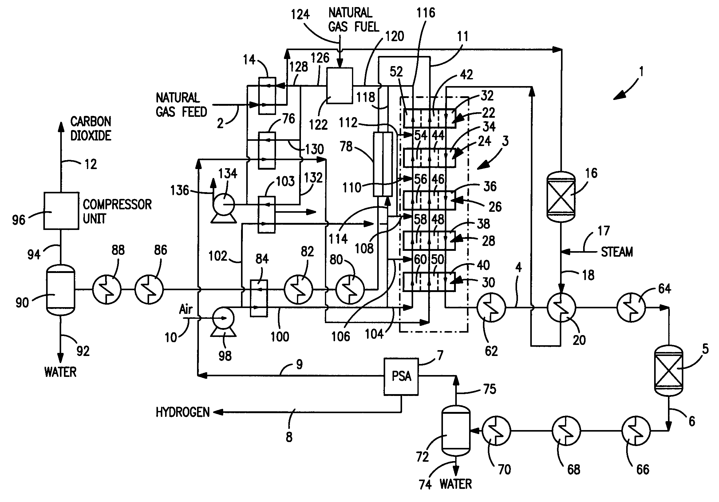
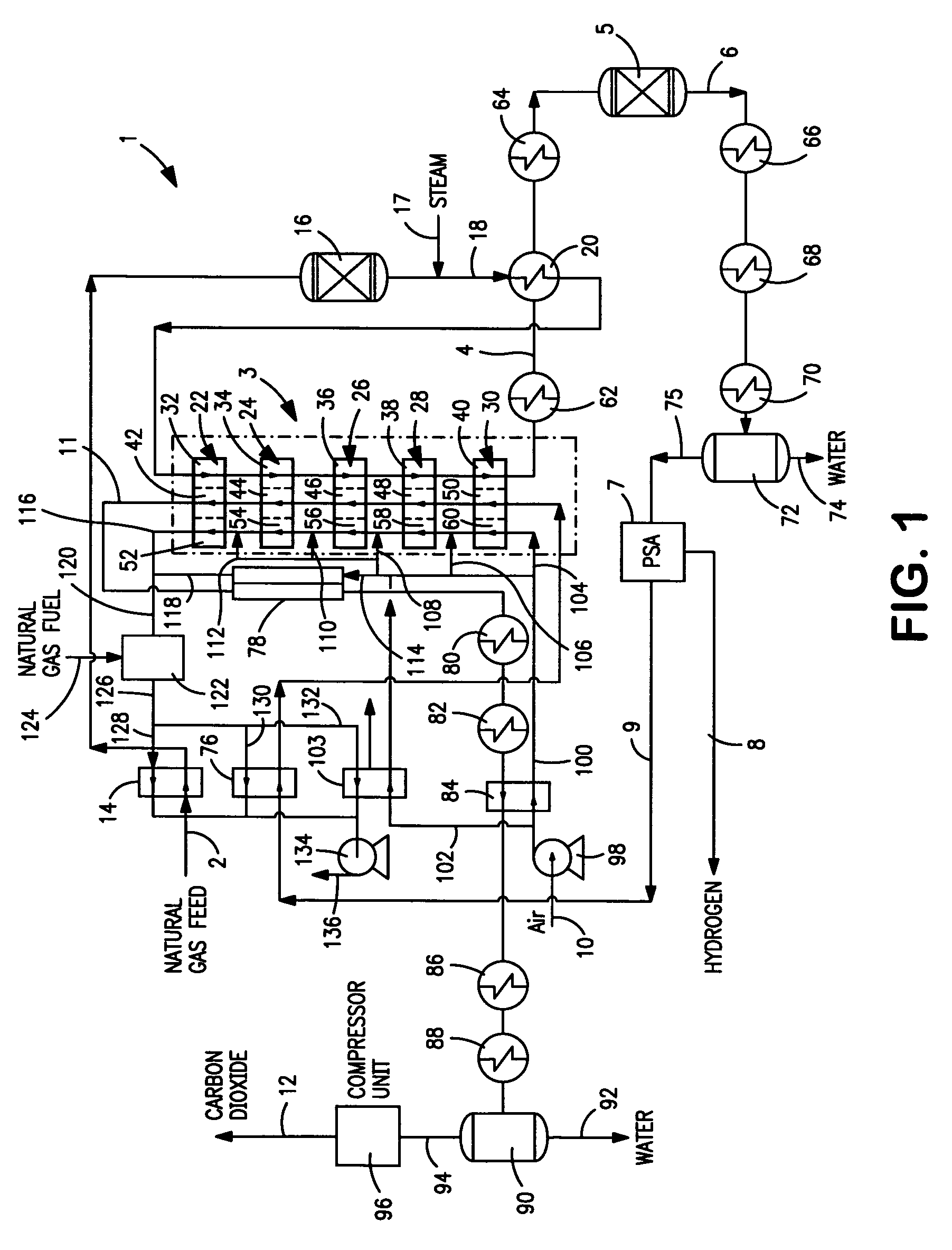
[0044]With reference to FIG. 1, a hydrogen production facility 1 is illustrated that is used in the generation of hydrogen. However, it is understood that such environment for the present invention is for illustrative purposes only and that the present invention has a wider applicability.

[0045]Briefly, a hydrocarbon containing stream 2 that as illustrated can be natural gas, but potentially any stream containing one or more hydrocarbons to be subjected to steam methane reforming reactions, is conducted to a reactor 3 to produce a synthesis gas stream 4 containing hydrogen, carbon dioxide, carbon monoxide, water and trace amounts of unreacted hydrocarbons. The hydrogen content of synthesis gas stream 4 is increased within a known water-gas shift reactor 5 and hydrogen is separated from the resulting shifted stream 6 in a known pressure swing adsorption unit 7 having beds of adsorbent, operating out of phase, to separate hydrogen from such stream and thereby to produce a hydrogen stre...


PUM

PropertyMeasurementUnit
temperatureaaaaaaaaaa

Abstract

A method and apparatus for reacting a hydrocarbon containing feed stream by steam methane reforming reactions to form a synthesis gas. The hydrocarbon containing feed is reacted within a reactor having stages in which the final stage from which a synthesis gas is discharged incorporates expensive high temperature materials such as oxide dispersed strengthened metals while upstream stages operate at a lower temperature allowing the use of more conventional high temperature alloys. Each of the reactor stages incorporate reactor elements having one or more separation zones to separate oxygen from an oxygen containing feed to support combustion of a fuel within adjacent combustion zones, thereby to generate heat to support the endothermic steam methane reforming reactions.

Description

U.S. GOVERNMENTAL INTEREST[0001]This invention was made with United States Government support under Cooperative Agreement number DE-FC26-01NT41096 awarded by the U.S. Department of Energy, National Energy Technology Laboratory. The United States Government has certain rights in this invention.FIELD OF THE INVENTION[0002]The present invention relates to a method and apparatus for producing a synthesis gas in which a hydrocarbon containing stream and steam are reacted by steam methane reforming reactions conducted in reaction stages to produce the synthesis gas and the temperature within each of the reaction stages is controlled to minimize the use of expensive, high-temperature alloys. More particularly, the present invention relates to such a method and apparatus in which the reaction stages are heated by oxy-fuel combustion involving the use of oxygen transport membranes to supply the oxygen. Even more particularly, the present invention relates to such a method and apparatus in wh...

Claims


Application Information

Patent Timeline
Patent Type & Authority Patents(United States)
IPC IPC(8): C01B3/32
CPCB01J8/009B01J8/0426B01J8/0442B01J8/0492B01J8/0496B01J8/062B01J8/067B01J12/007B01J19/248C01B3/382C01B3/384C01B3/48C01B13/0251B01J2208/00309B01J2208/00504B01J2208/0053B01J2208/00548B01J2219/0004B01J2219/00117B01J2219/00157B01J2219/00159B01J2219/00164B01J2219/182B01J2219/1923C01B2203/0233C01B2203/0283C01B2203/043C01B2203/0495C01B2203/0811C01B2203/141C01B2203/143C01B2203/1614C01B2203/86C01B2210/0046Y02P30/00
Inventor HEMMINGS, JOHN WILLIAMBONNELL, LEOROBINSON, EARL T.
Owner PRAXAIR TECH INC
Why Eureka
Try Eureka