Tandem continuous channel electron multiplier

a continuous channel electron multiplier and continuous channel technology, applied in the direction of electron multiplier tubes, multiplier electrode arrangements, electric discharge tubes, etc., can solve the problems of loss of detection efficiency of multiple channel electron multipliers, less stable operation of single channel cem high output current,

Active Publication Date: 2010-03-30
ADAPTAS SOLUTIONS LLC
View PDF8 Cites 1 Cited by
  • Summary
  • Abstract
  • Description
  • Claims
  • Application Information

AI Technical Summary

Problems solved by technology

In addition, the single channel CEM high output current operation is less stable than a multiple channel electron multiplier.
However, a multiple channel electron multiplier suffers losses in detection efficiency due to an inactive area between the channels at the input beam end.

Method used


Image

  • Tandem continuous channel electron multiplier
  • Tandem continuous channel electron multiplier
  • Tandem continuous channel electron multiplier

Examples


Embodiment Construction

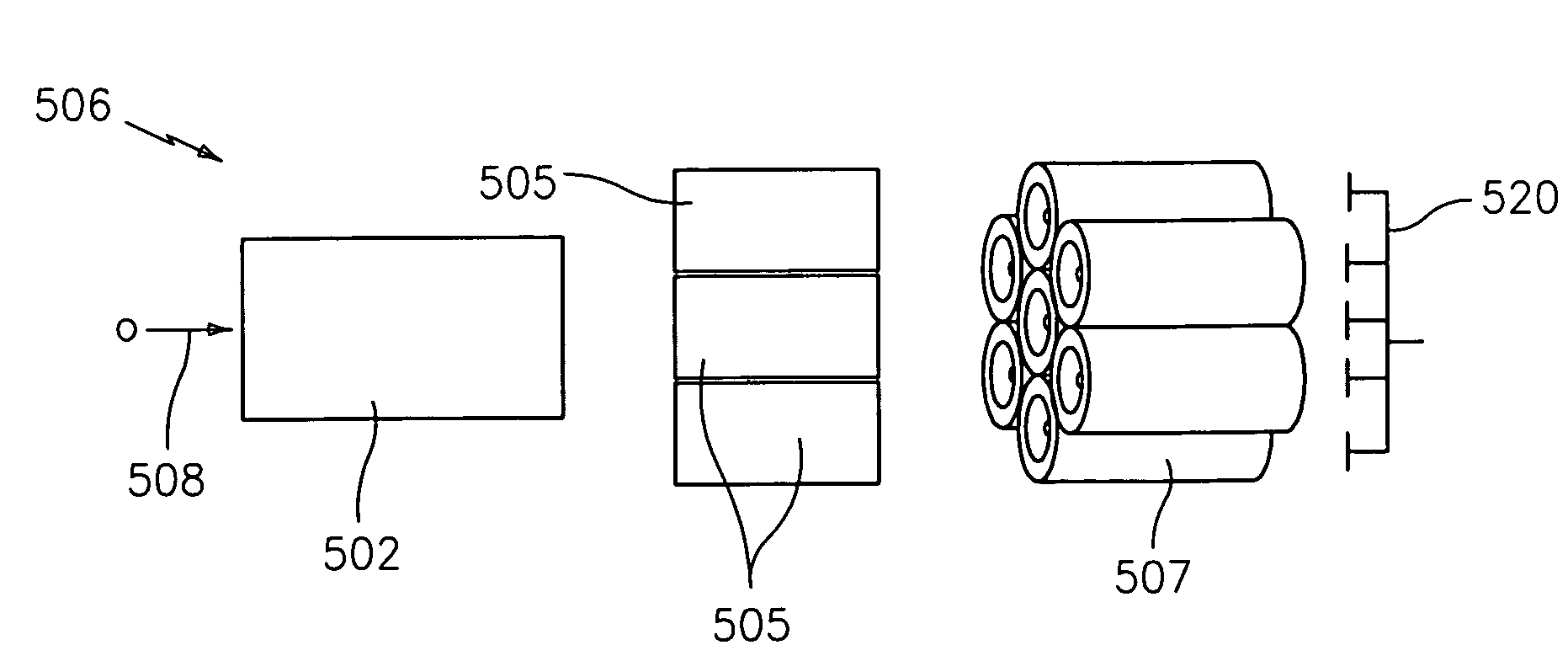
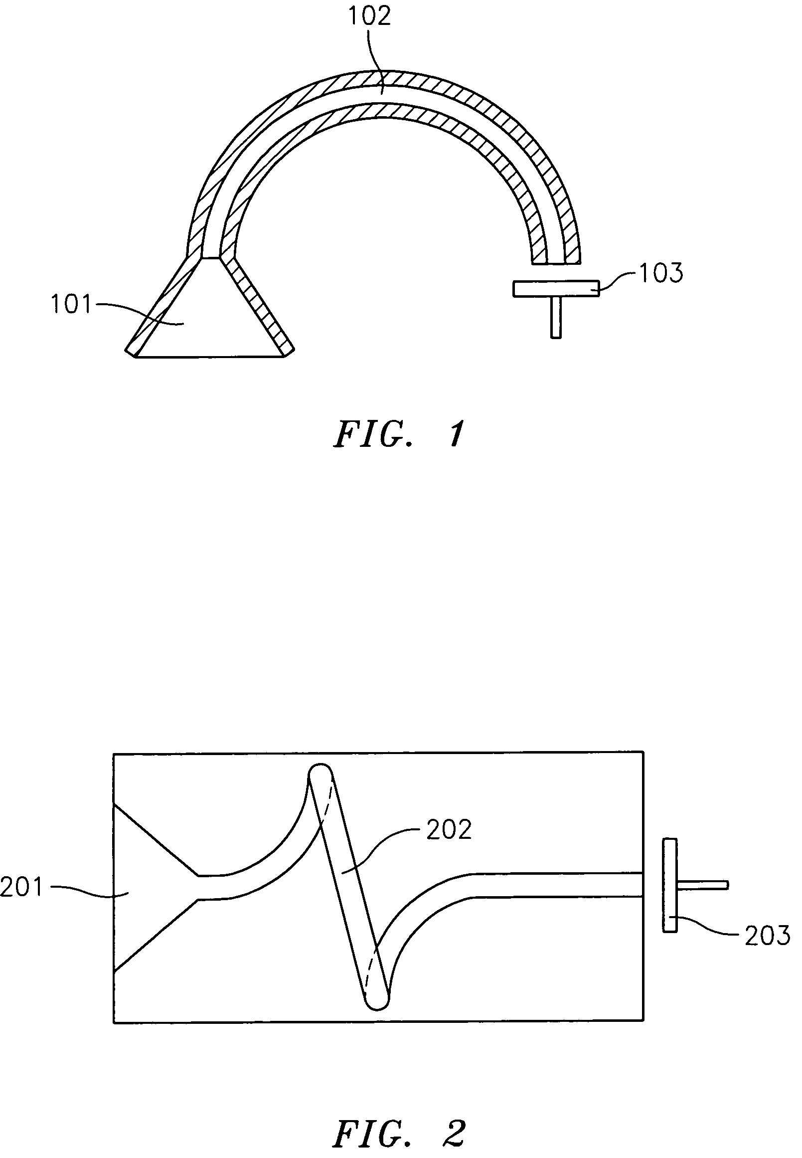
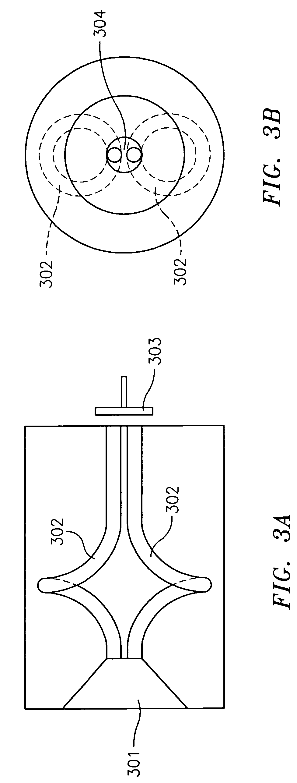
[0014]FIG. 1 shows an exemplary conventional CEM. Most CEMs include an input funnel cone 101, a curved tubular channel 102, and a Faraday cup 103 as shown in FIG. 1. FIG. 2 shows an alternate CEM having an input funnel 201, spiraled, tubular channel 202 and Faraday cup 203. FIG. 3A depicts a conventional CEM having an input funnel 301, multiple curved channels 302 and Faraday cup 303. FIG. 3B is a front view of the CEM in FIG. 3A.

[0015]FIG. 4 is an enlarged view of a portion of FIG. 2 illustrating the operation of the CEM. The CEM inside channel wall 401 is prepared with an electron emissive layer 402, most commonly SiO2, on top of a semi-conducting layer 403, most commonly reduced lead-oxide glass. The funnel cone 201 attached to the tubular channel 202 increases detection sensitivity due to a larger incoming particle beam profile acceptance.

[0016]When a charged particle, photon, or energetic neutral particle strikes the surface of the input end of a CEM, secondary electrons are ge...


PUM


Abstract

A channel electron multiplier including a single channel CEM for receiving an input particle. A multi-channel CEM is positioned after the single channel CEM for receiving emissions from the single channel CEM. An electron collector is positioned after the multi-channel CEM for generating a pulse current in response to emissions from the multi-channel CEM.

Description

BACKGROUND OF THE INVENTION[0001]Channel electron multipliers (CEMs) are used to amplify charged particle, photon, or energetic neutral particle signals. CEMs are used to detect photons, charged particles both positive and negative, and energetic neutral particles. They are used as detectors in mass spectrometers as well as in surface analyzers such as auger and x-ray / ultraviolet photoelectron spectrometers, and are also employed in electron microscopes. In addition, they can also be used for electron multiplication in a photon multiplier application.[0002]The CEM makes use of an emissive surface to generate electron multiplication. The emissive surface will emit secondary electrons when struck by a charged particle, or energetic neutral particle, or photon, with sufficient energy. This process is repeated and generates an electron avalanche down the length of the channel. An electron collector, such as a Faraday cup, at the end of the channel collects the electrons and converts the...

Claims


Application Information

Patent Timeline
Patent Type & Authority Patents(United States)
IPC IPC(8): H01J43/04
CPCH01J43/246H01J43/04H01J43/06
Inventor HOSEA, KIKI H.BREUER, MATTHEW L.
Owner ADAPTAS SOLUTIONS LLC
Why Eureka
Try Eureka