Electronic ID tag and co-operating antenna

a technology of cooperating antennas and id tags, which is applied in the direction of antennas, geological measurements, reradiation, etc., can solve the problems of affecting the attachment of id tags in pipes, id tags are subjected to wear, and the signals from id tags are relatively small, so as to achieve rational maintenance and control the use of individual components

Active Publication Date: 2010-03-30
TRAC ID SYST
View PDF14 Cites 18 Cited by
  • Summary
  • Abstract
  • Description
  • Claims
  • Application Information

AI Technical Summary

Benefits of technology

[0017]In order to improve the range of the signals from the electronic ID tag, there are arranged between the adjacent antenna and the identifiable chip, and between the identifiable chip and a ground-plane plate, impedance-matched inductances. Also in order to improve the range in varying temperatures, there is used for the adjacent antenna a material which has both a very low dielectric loss and, at the same time, a stable dielectric constant at varying temperatures, combined with a very low thermal expansion coefficient.
[0039]It may also be advantageous to place electronic equipment outside the ring, for example in a specially approved explosion-proof box. Thereby it is possible to avoid the entire ring having to be in an explosion-proof embodiment.

Problems solved by technology

This positioning entails that the ID tags are subjected to wear during the moving of the pipe in the borehole and to damage from, for example, power tongs during make-up and break-out operations.
It has also turned out that the attachment of the ID tags in the pipes is adversely affected by relatively large pressure variations in the well.
Equipment according to prior art exhibits drawbacks related to applicability and / or reliability, as, among other things, the range of signals from the ID tags is relatively small, the ID tags are subjected to wear and may be damaged during the assembling of the pipes.

Method used


Image

  • Electronic ID tag and co-operating antenna
  • Electronic ID tag and co-operating antenna
  • Electronic ID tag and co-operating antenna

Examples


Embodiment Construction

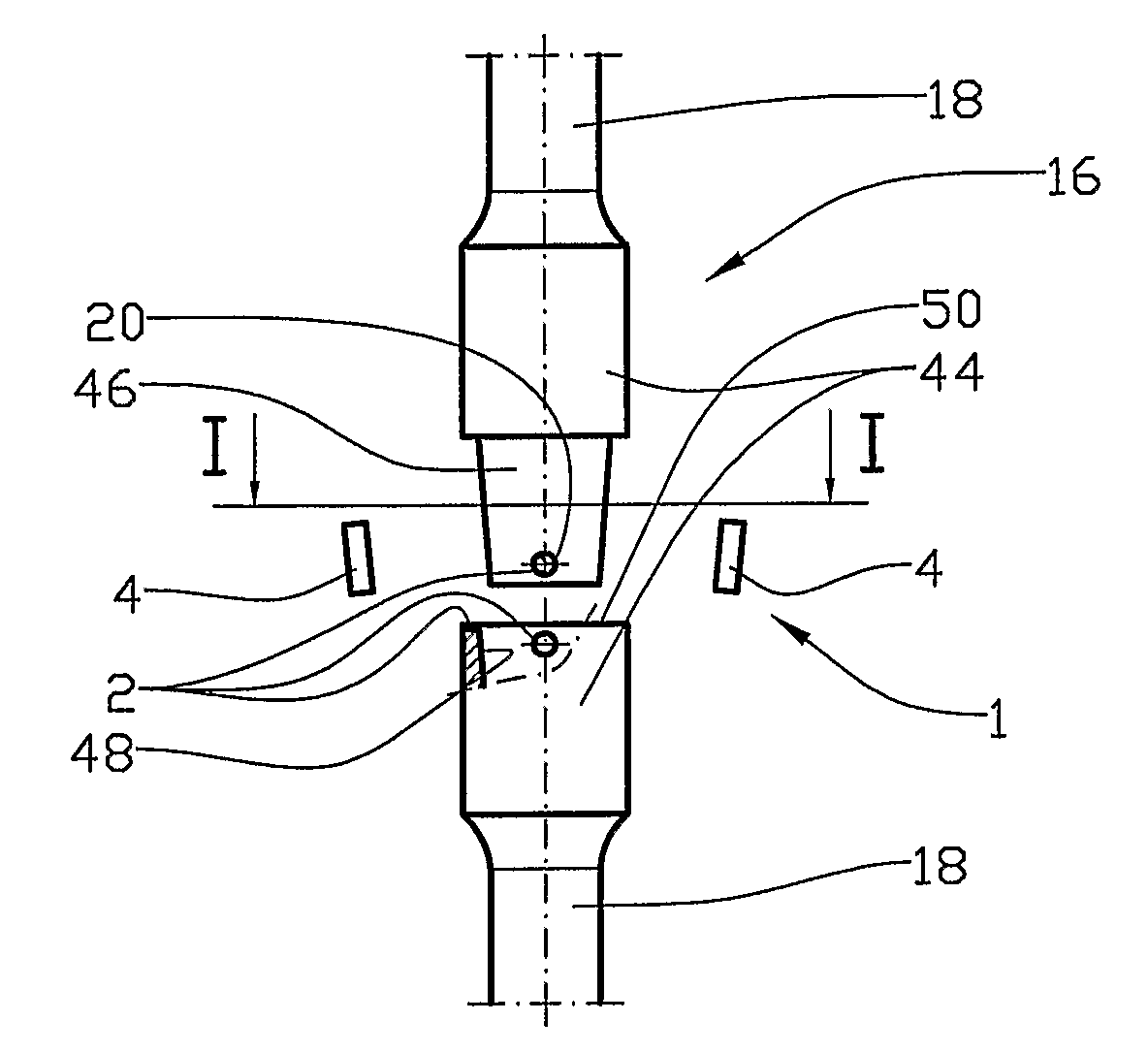
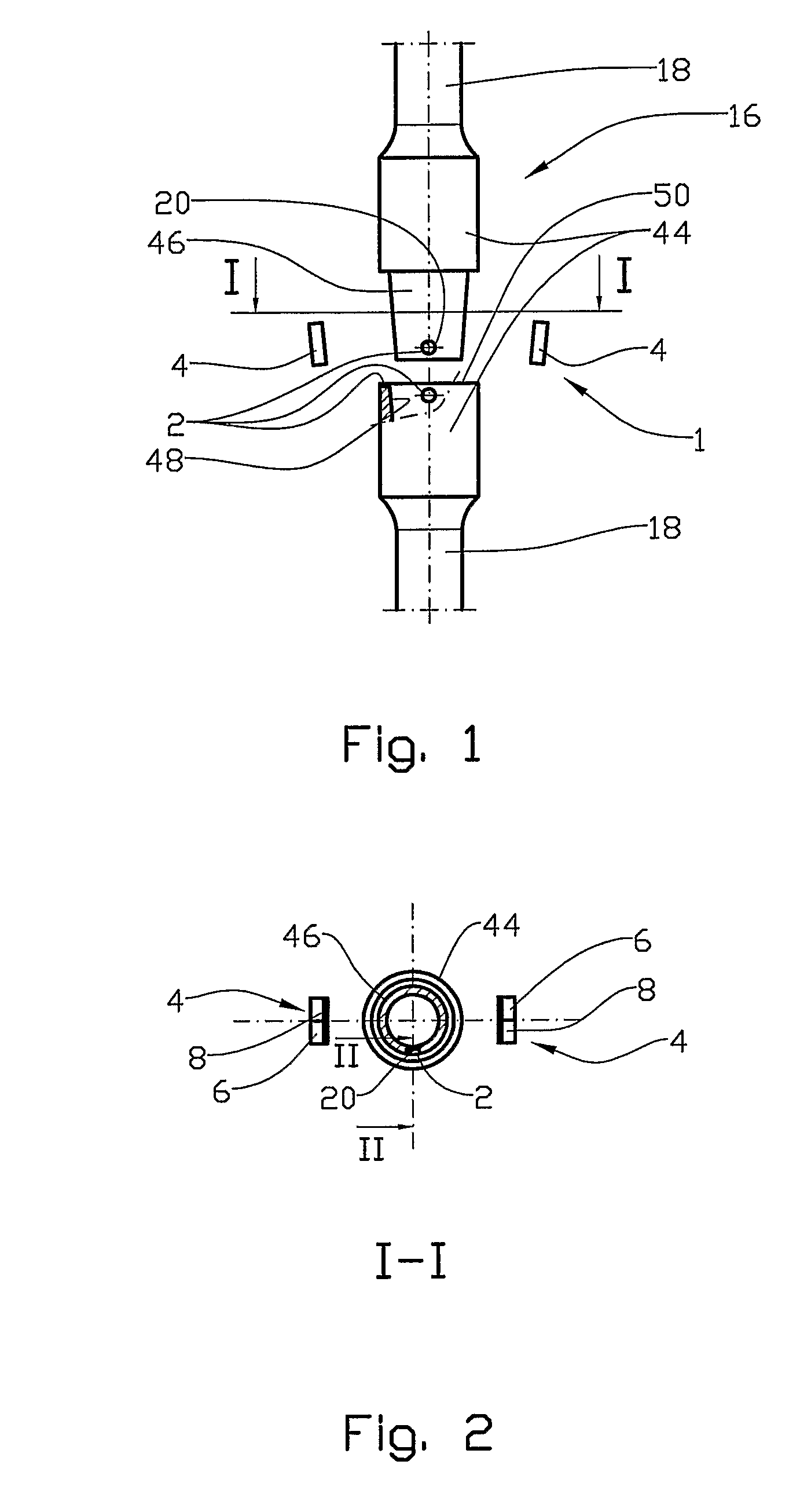
[0047]In the drawings the reference numeral 1 denotes an antenna distantly located relative to the reading position of an electronic ID tag 2. In this preferred embodiment this distant antenna 1 is provided with two partial antennas 4, each comprising a transmitting antenna 6 and a receiving antenna 8.

[0048]The partial antennas 4 are distributed about the expected reading position of the electronic ID tag 2 and are attached to a suitable body, not shown.

[0049]The distant antenna 1 is connected to necessary amplifiers and data processing apparatuses, not shown.

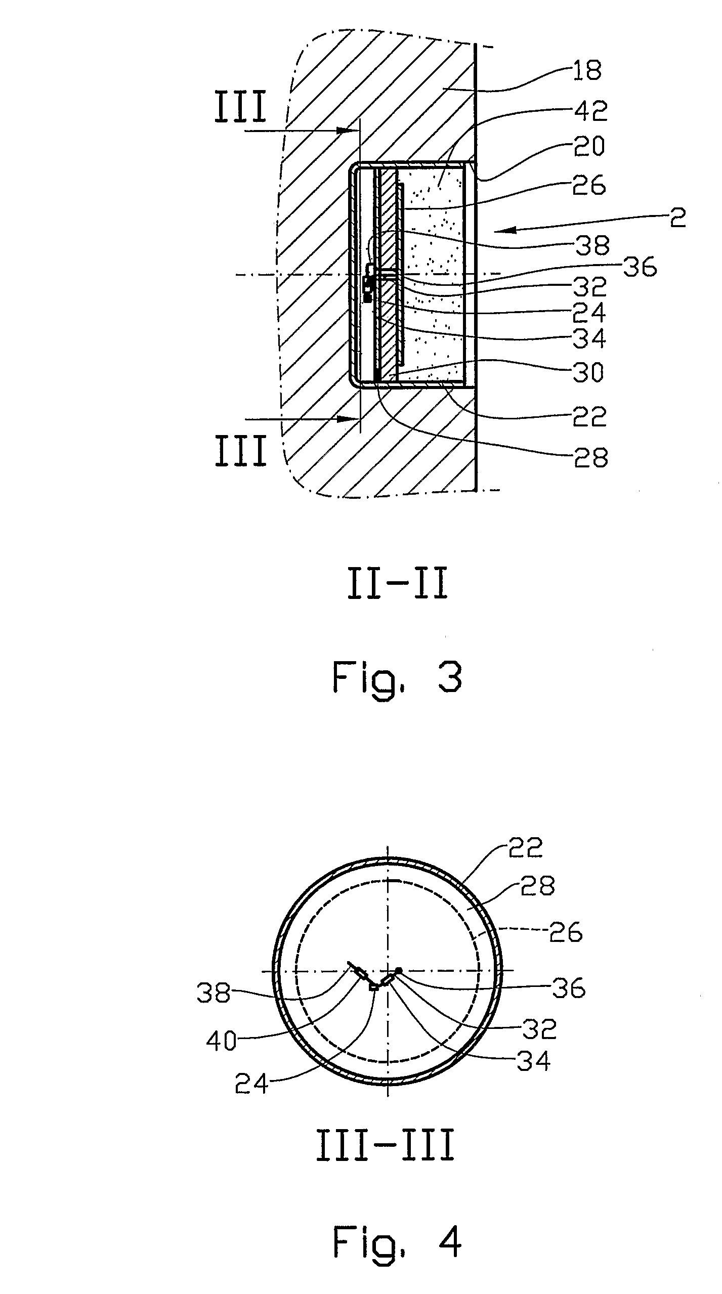
[0050]In a pipe string, or a casing 16, including pipes or casings 18 (bodies) screwed together, each of the pipes 18 is provided with a tag recess 20, in which the electronic ID tag 2 is disposed, see FIG. 3.

[0051]The electronic ID tag 2 includes, in addition to a cup-like housing 22 which is made of an electrically conductive material, an identifiable chip 24, an adjacent antenna 26, a ground-plane plate 28 and an electricall...


PUM


Abstract

An electronic ID tag (2) for mounting in a body (18), in which at least the identity of the body (18) is to be remotely readable, the electronic ID tag (2) including an identifiable chip (24) which is electrically connected to at least one adjacent antenna (26), the identifiable chip (24) being arranged to receive energy via the adjacent antenna (26) and by means of this energy to transmit, via the adjacent antenna (26), a signal including the identity of the electronic ID tag to a distant antenna (1), and there being arranged, between the adjacent antenna (26) and the identifiable chip (24) and between the identifiable chip (24) and a ground-plane plate (28) impedance-matched inductances (34, 40), the electronic ID tag (2) being placed, with advantage, in the box portion or pin (44) of a body (18), whereby it is protected against mechanical wear.

Description

CROSS REFERENCE TO RELATED APPLICATIONS[0001]This application claims benefit of PCT Application Serial Number PCT / NO2005 / 000373 filed on Oct. 10, 2005, Norwegian Application Serial Number 20054257 filed on Sep. 15, 2005 and Norwegian Application Serial Number 20044356 filed on Oct. 13, 2004.STATEMENT REGARDING FEDERALLY SPONSORED RESEARCH OR DEVELOPMENT[0002]Not ApplicableTHE NAMES OF THE PARTIES TO A JOINT RESEARCH AGREEMENT[0003]Not ApplicableINCORPORATION-BY-REFERENCE OF MATERIAL SUBMITTED ON A CD[0004]Not ApplicableBACKGROUND OF THE INVENTION[0005]1. Technical Field[0006]This invention relates to an electronic ID tag and a co-operating antenna. More particularly, it concerns an electronic ID tag including an identifiable data chip connected to an adjacent antenna, and a co-operating distant antenna. Between the adjacent antenna and the identifiable chip, and between the identifiable chip and a ground-plane plate are arranged impedance-matched inductances. The electronic ID tag m...

Claims


Application Information

Patent Timeline
Patent Type & Authority Patents(United States)
IPC IPC(8): G08B13/14E21B17/00G06KG06K19/04G06K19/07
CPCE21B17/006G06K19/04G06K19/0723G01S13/751G01V15/00G06K19/077E21B47/13
Inventor STAFF, FINN
Owner TRAC ID SYST
Why Eureka
Try Eureka