Volumetric direction-finding system using a Luneberg Lens

a technology of luneberg lens and luneberg axis, which is applied in the direction of direction finders, instruments, measurement devices, etc., can solve the problem of limited real-estate of the antenna subsystem, and achieve the effect of high gain, high precision and high sensitivity

Inactive Publication Date: 2010-03-30
OXLEY ROGER DALE
View PDF10 Cites 26 Cited by
  • Summary
  • Abstract
  • Description
  • Claims
  • Application Information

AI Technical Summary

Benefits of technology

[0015]This invention utilizes a single multi-beam antenna aperture that offers instantaneous wide RF bandwidth, hemispheric volume coverage, and beam-forming for high gain—high sensitivity, for signal detection and precision direction-finding (DF). This antenna system incorporates a spherical lens, with the lens focal surface near-uniformly covered with a spherical array of frequency-independent (br

Problems solved by technology

Most operational platforms, particularly naval and air pl

Method used


Image

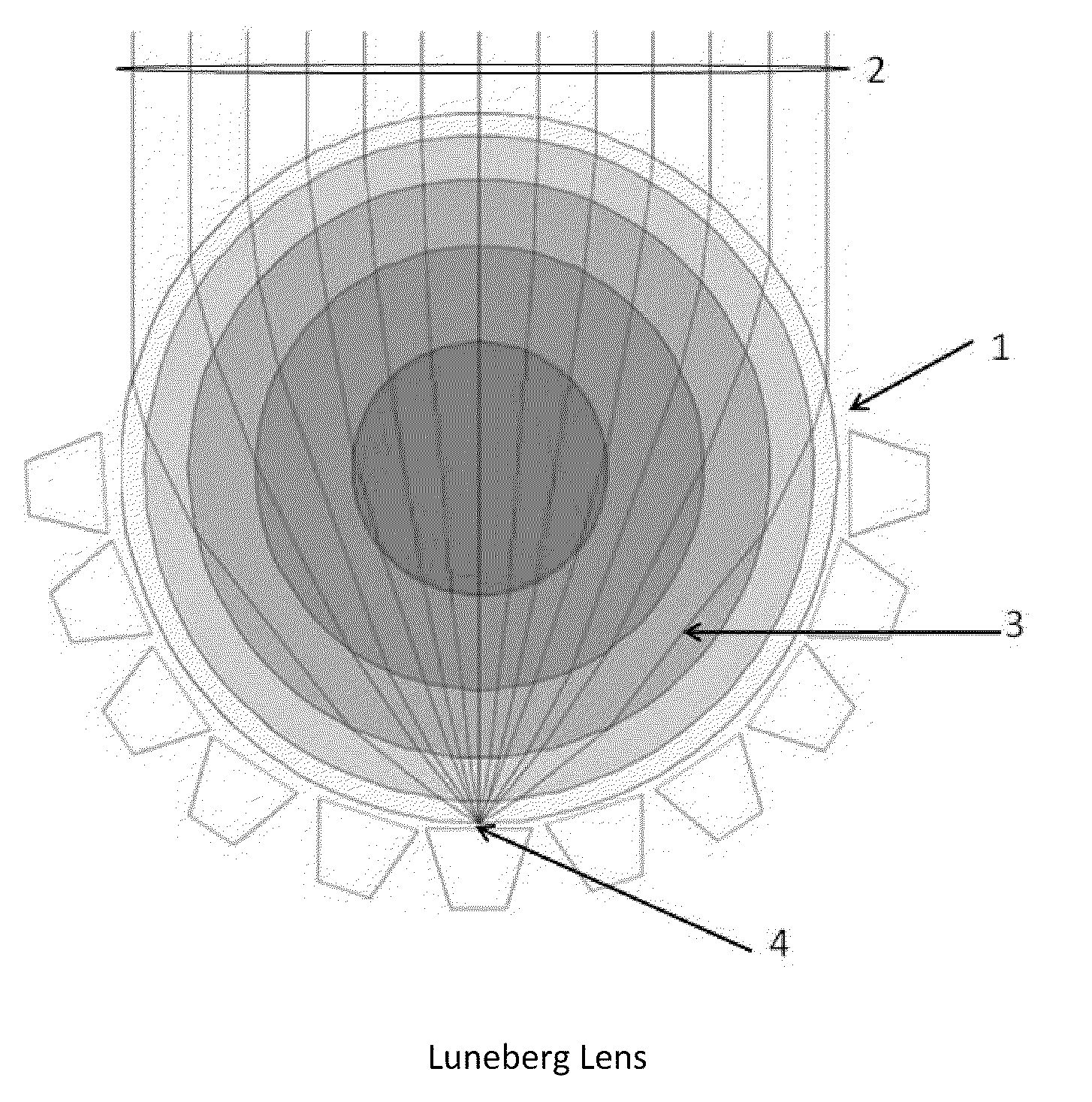
  • Volumetric direction-finding system using a Luneberg Lens
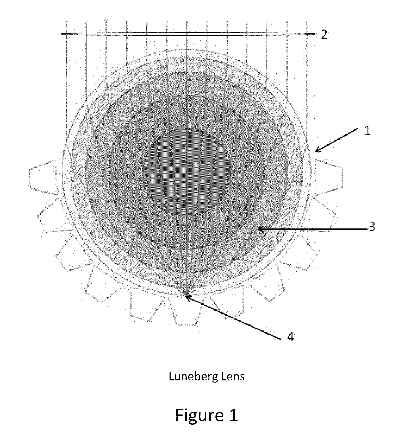
  • Volumetric direction-finding system using a Luneberg Lens
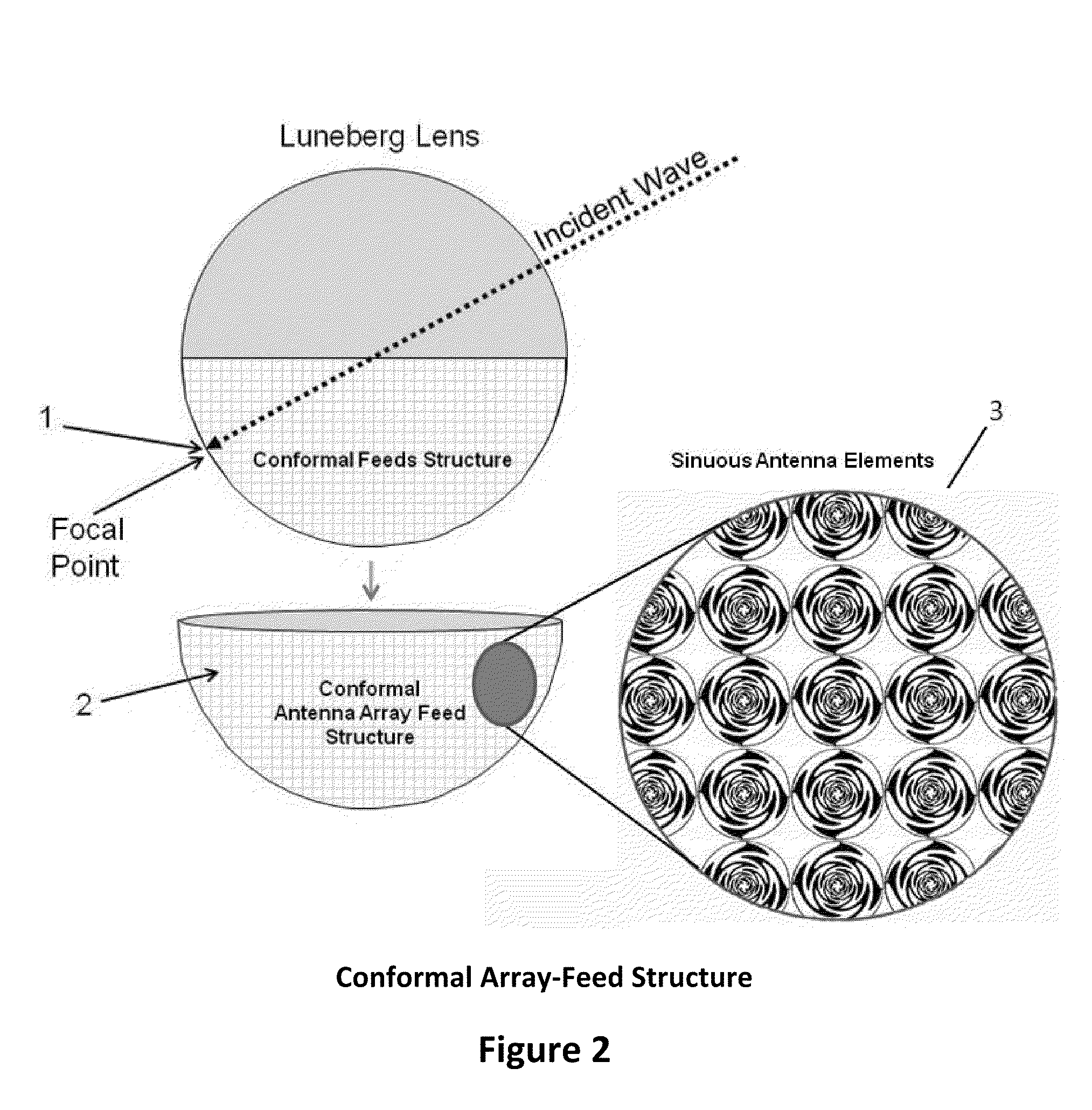
  • Volumetric direction-finding system using a Luneberg Lens

Examples


Embodiment Construction

[0031]The RF spectrum of today is increasingly dense with the rapid introduction of commercial, civil and military emissions, which has placed extreme demands on military situation awareness and early-warning equipment and missions. The modern weapon and delivery systems have evolved to be silent and stealthy, and weapons are able to cruise at supersonic / hypersonic speeds. Many of these threats employ low-probability-of-intercept (LPI) technology to further evade detection. Similarly, reconnaissance and surveillance activities are hampered, lacking bandwidth, high sensitivity systems with direction finding; to address complex scan-on-scan issues. Detecting and analyzing signals of special interest is increasingly difficult.

[0032]Addressing these operation issues require system architectures which can instantaneously look in all hemispheric directions while monitoring the full frequency coverage (typically several GHz), have considerable antenna gain (on the order of 100:1 or better)...


PUM


Abstract

Disclosed is an Radio Frequency (RF) receiving system methodology, utilizing an Luneberg Lens having a spherically shaped outer surface and a semi-spherical shaped focal surface composed of near-equally spaced frequency-independent antenna elements disposed uniformly to cover the semi-spherical focal surface of the Luneberg Lens; and radio frequency (RF) power splitters and combiners for combining the RF energy received by the antenna elements; forming rows and columns; thereby reducing the number of required RF receiver channels for subsequent processing, where the maximum row/column and differential amplitude comparison is used for deriving volumetric direction finding (DF) of intercepted signals; as part of a robust signal detection and direction-finding (DF) system; for detecting and processing a plurality of signals emanating from surface and airborne platforms within the hemisphere, where each surface and airborne platform include transmitters for transmitting navigation, communication and radar signals.

Description

CROSS-REFERENCE TO RELATED APPLICATIONS[0001]No prior application claim.STATEMENT REGARDING FEDERALLY SPONSORED RESEARCH OR DEVELOPMENT[0002]Mr. Roger Dale Oxley is the sole owner with full rights of this invention, developed without any federally sponsored research and development funding or resources.REFERENCE TO SEQUENCE LISTING, A TABLE, OR A COMPUTER PROGRAM COMPACT DISK APPENDIX[0003]No separate materials listing, tables or computer program CD was submitted.BACKGROUND OF THE INVENTION[0004]1. Technical Field[0005]The RF spectrum is increasingly dense and complex, with expanding introduction of commercial, civil and military emissions, which places extreme demands on the reconnaissance, surveillance and early-warning equipment and missions. The modern weapons and delivery systems have also evolved to be increasingly silent and stealthy, with supersonic / hypersonic delivery speeds, placing naval platforms at high risk. As a result, the need for simultaneous wide-instantaneous-ban...

Claims


Application Information

Patent Timeline
IPC IPC(8): G01S5/04G01S13/00
CPCG01S3/043G01S3/28
Inventor OXLEY, ROGER DALE
Owner OXLEY ROGER DALE
Why Eureka
Try Eureka