
High temperature solar receiver

a solar receiver and high temperature technology, applied in solar thermal energy generation, solar heat systems, solar light sources, etc., can solve the problems of relatively low thermodynamic efficiency of rankine cycles at moderate maximum temperatures, low conversion efficiency, etc., and achieve the effect of reducing radiant thermal loss

Inactive Publication Date: 2010-04-06
BRIGHTSOURCE ENERGY
View PDF73 Cites 26 Cited by
  • Summary
  • Abstract
  • Description
  • Claims
  • Application Information

AI Technical Summary

Benefits of technology

"The invention provides a solar receiver that can heat a working fluid to high temperatures using concentrated solar radiation. The receiver has multiple layers of surface that are used to heat the fluid, and a depth-loading configuration helps trap the heat and reduce radiant thermal loss. The receiver includes a plurality of optically transparent elements that lie along a sealed fluid channel connected to a housing. The elements can be arranged in a bed within the housing and may be at least partially optically transparent. The housing includes an array of tubes that allow concentrated light to be focused thereon from a range of angles. The tubes are arranged in layers, with some layers having higher absorption rates of solar radiation than others. The tubes are connected to inlet and outlet flow headers, and some may be reinforced with reinforcing winds. A controller is provided to detect temperatures of the tubes and control the flow of cooling fluid responsively. Overall, the invention provides a more efficient and effective solar receiver for heating fluids."

Problems solved by technology

Systems based on cylindrical parabolic trough mirrors such as those which were built in the Mojave Desert in California in the 1980s were financially successful because of governmental subsidies in the form of tax breaks and preferential electricity tariffs, but suffer from relatively low conversion efficiencies both because of the necessity to invest significant energy in the circulation of a synthetic oil used as the working fluid for heat absorption, and because of the relatively low thermodynamic efficiency of the Rankine cycle at the moderate maximum temperatures allowed by the synthetic oil.

Method used


Image

  • High temperature solar receiver
  • High temperature solar receiver
  • High temperature solar receiver

Examples


Embodiment Construction

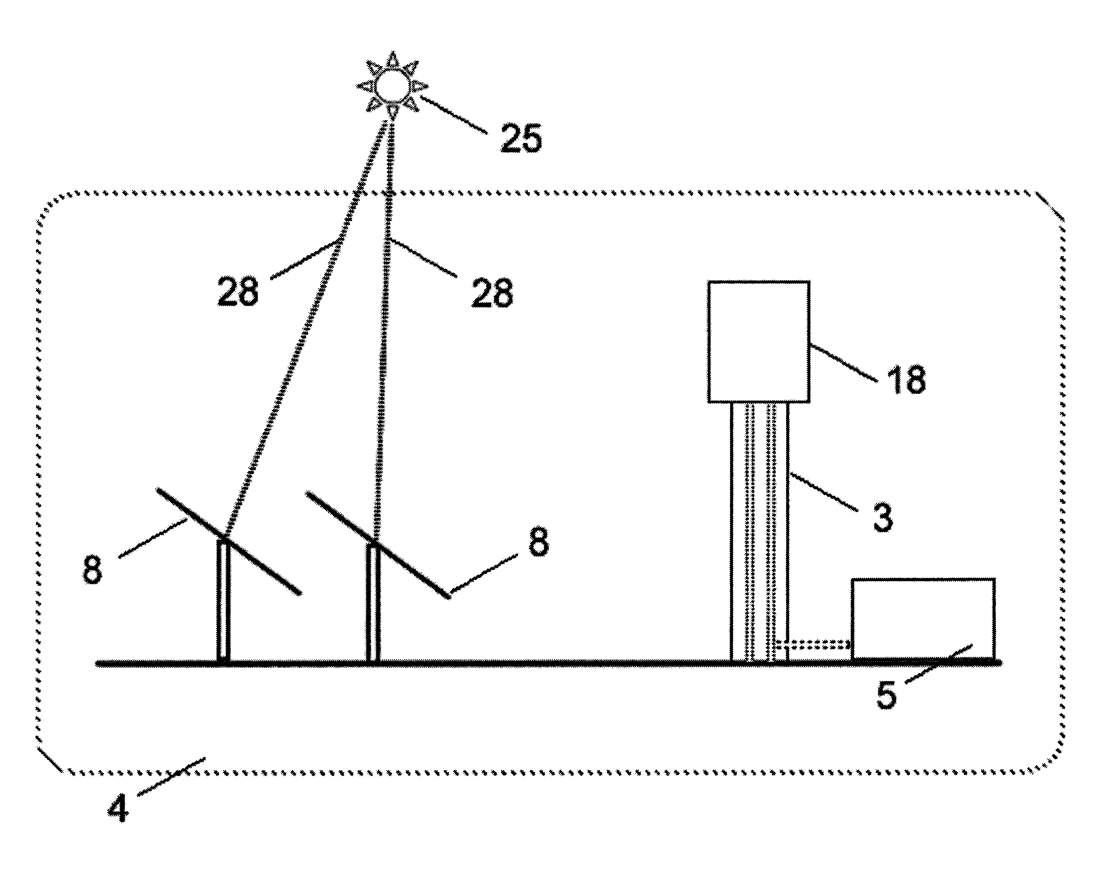
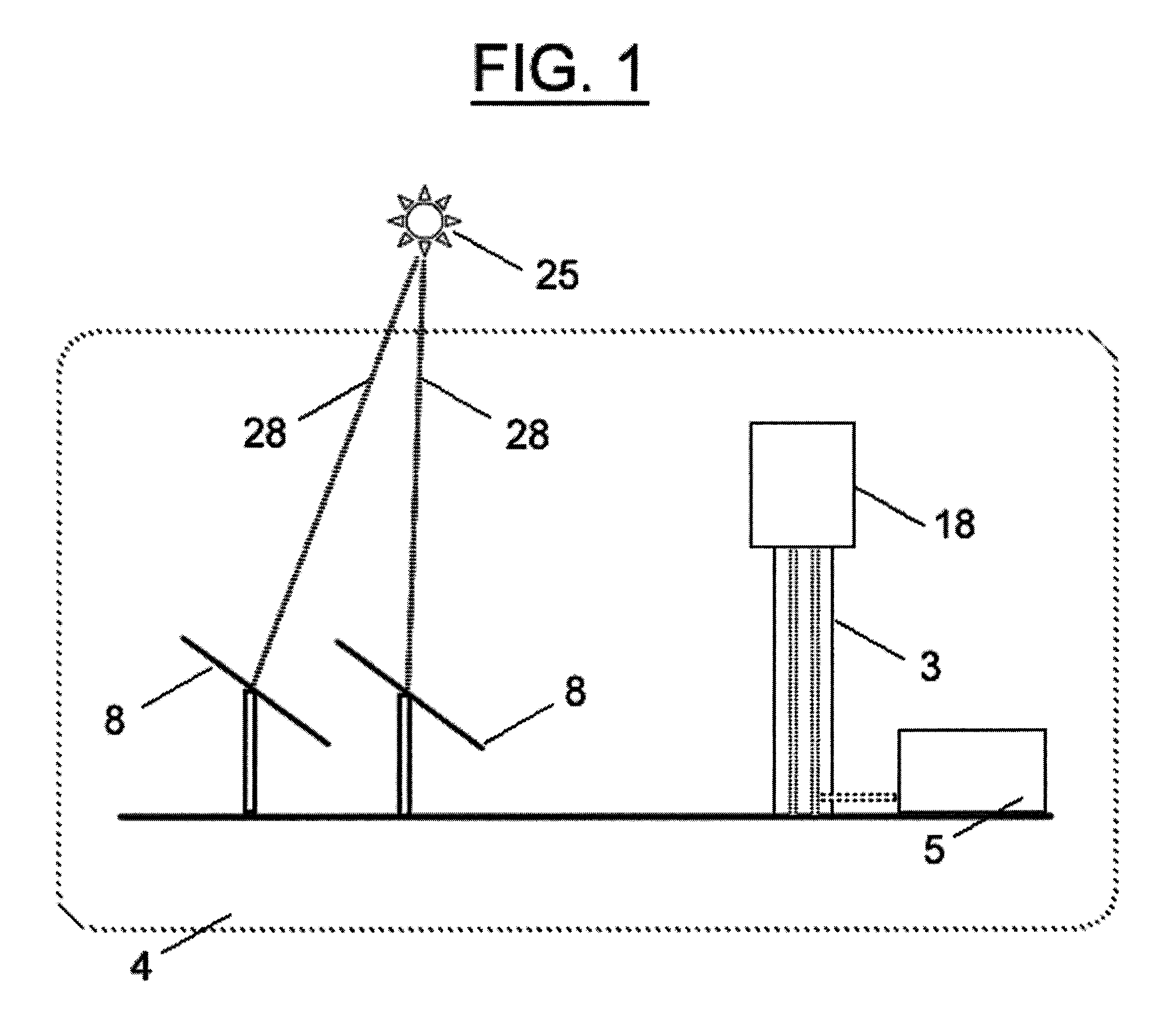
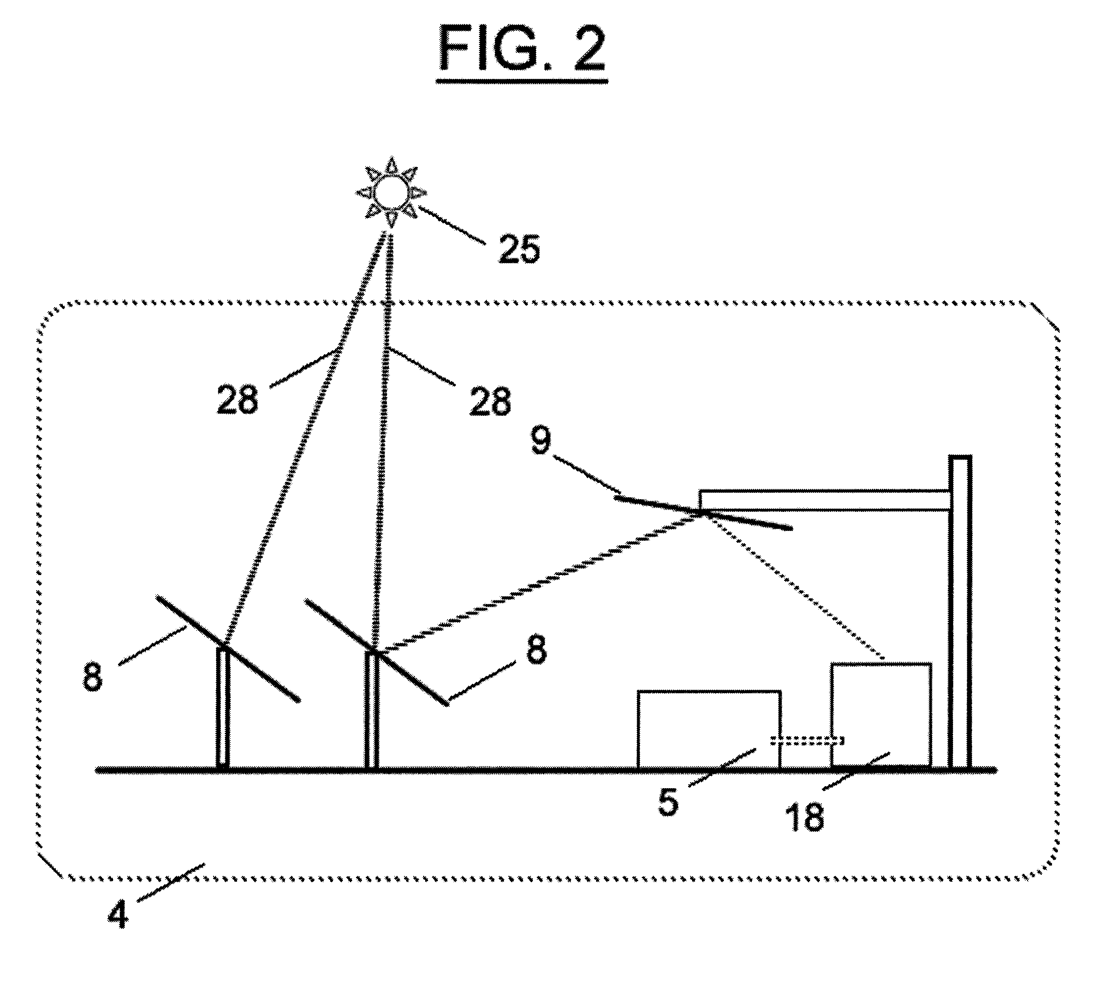
[0034]FIG. 1 shows a solar power system 4 in which heliostat-mounted mirrors 8 reflect incident solar radiation 28 onto a receiver 18 in which a working fluid (not shown) is heated for later use in an electric power generating plant 5. The heliostat-mounted mirrors 8 are capable of tracking the apparent movement of the sun 25 across the sky each day in order to maintain the reflective focus in the direction of the receiver 18 as the angle of the incident radiation 28 changes. The receiver 18 is located atop a tower 3, or in an alternative embodiment, shown in FIG. 2, is located on the ground, and the heliostat-mounted mirrors 8 reflect solar radiation onto one or more mirrors 9 which further reflect the radiation onto the receiver 18.

[0035]A receiver receives light both near its surface and deeper within. By progressively absorbing the light and converting it to heat energy both near the surface and deeper within the receiver, the energy can be captured and transferred to a working ...


PUM


Abstract

The invention provides receivers which can be used to heat a working fluid to high temperature. In preferred embodiments, concentrated solar radiation is received and converted to heat at varying depths in the receiver such that multiple layers of surface are used to heat the working fluid. In addition, the depth-loading configuration helps to trap received heat to reduce radiant thermal loss.

Description

CROSS REFERENCE TO RELATED APPLICATIONS[0001]This application claims priority to U.S. provisional patent application Ser. No. 60 / 747,087 filed 11 May 2006, which expires May 11, 2007.FIELD OF THE INVENTION[0002]This invention relates to the conversion of solar radiation to electric power and devices therefor, as well as related processes, components, articles of manufacture, and other technological improvements.BACKGROUND[0003]The generation of electric power from thermal energy absorbed from solar radiation has been proposed as an alternative or complementary technological approach to the burning of fossil fuels, with societal benefits accruing from reduction in emissions from combustion, from reduced reliance on limited nonrenewable resources, and from the alleviation of political and ecological problems associated with the procurement and distribution of fossil fuels.[0004]Efficient utilization of the solar radiation resource is deemed necessary if solar electric power plants are...

Claims


Application Information

Patent Timeline
Patent Type & Authority Patents(United States)
IPC IPC(8): F24J2/24F24S10/70
CPCF24J2/07Y02E10/41F24S20/20Y02E10/40
Inventor GOLDMAN, ARNOLDMEITAV, ARIEHYAKUPOV, ILIAKROIZER, ISRAELKOKOTOV, YURIGILON, YOEL
Owner BRIGHTSOURCE ENERGY
Learn More