Thermal properties measurement apparatus

a technology of thermal properties and measurement apparatus, which is applied in the direction of material thermal analysis, computation using non-denominational number representation, complex mathematical operations, etc., can solve the problem of affecting the already existing temperature field, requiring vast calculations of the apparatus, and the inability to obtain the estimate of the conductivity distribution only from internal temperature measurements in the roi, etc. problem, to achieve the effect of simple measuremen

Inactive Publication Date: 2010-04-06
CHIKAYOSHI SUMI
View PDF29 Cites 15 Cited by
  • Summary
  • Abstract
  • Description
  • Claims
  • Application Information

AI Technical Summary

Benefits of technology

[0068]By utilizing the present invention, the unknown conductivity or transfer coefficient distribution in the ROI in the target can be measured from the measured temperature distributions in the ROI. Particularly, when already a temperature distribution exists in the ROI, the thermal conductivity or transfer coefficient distribution can be simply measured by measuring the temperature distribution without disturbing the temperature field.

Problems solved by technology

However, this apparatus requires the external thermal sources for realizing the temperature distributions.
This causes the problem that disturbs the already existing temperature field.
Furthermore, this apparatus requires vast calculation amounts because the conductivity distribution is estimated by updating the estimate using the sensitivity theorem such that the measured temperature data equal to the calculated data using the estimate.
Furthermore, for the calculation of the temperatures, the boundary conditions of the temperature and / or heat flux are required; then it was impossible to obtain the estimate of the conductivity distribution only from the internal temperature measurements in the ROI.

Method used


Image

  • Thermal properties measurement apparatus
  • Thermal properties measurement apparatus
  • Thermal properties measurement apparatus

Examples


Embodiment Construction

[0074]The following is explanation in detail of conduct forms of the present invention with referring to figures. The same component is referred to using the same reference number.

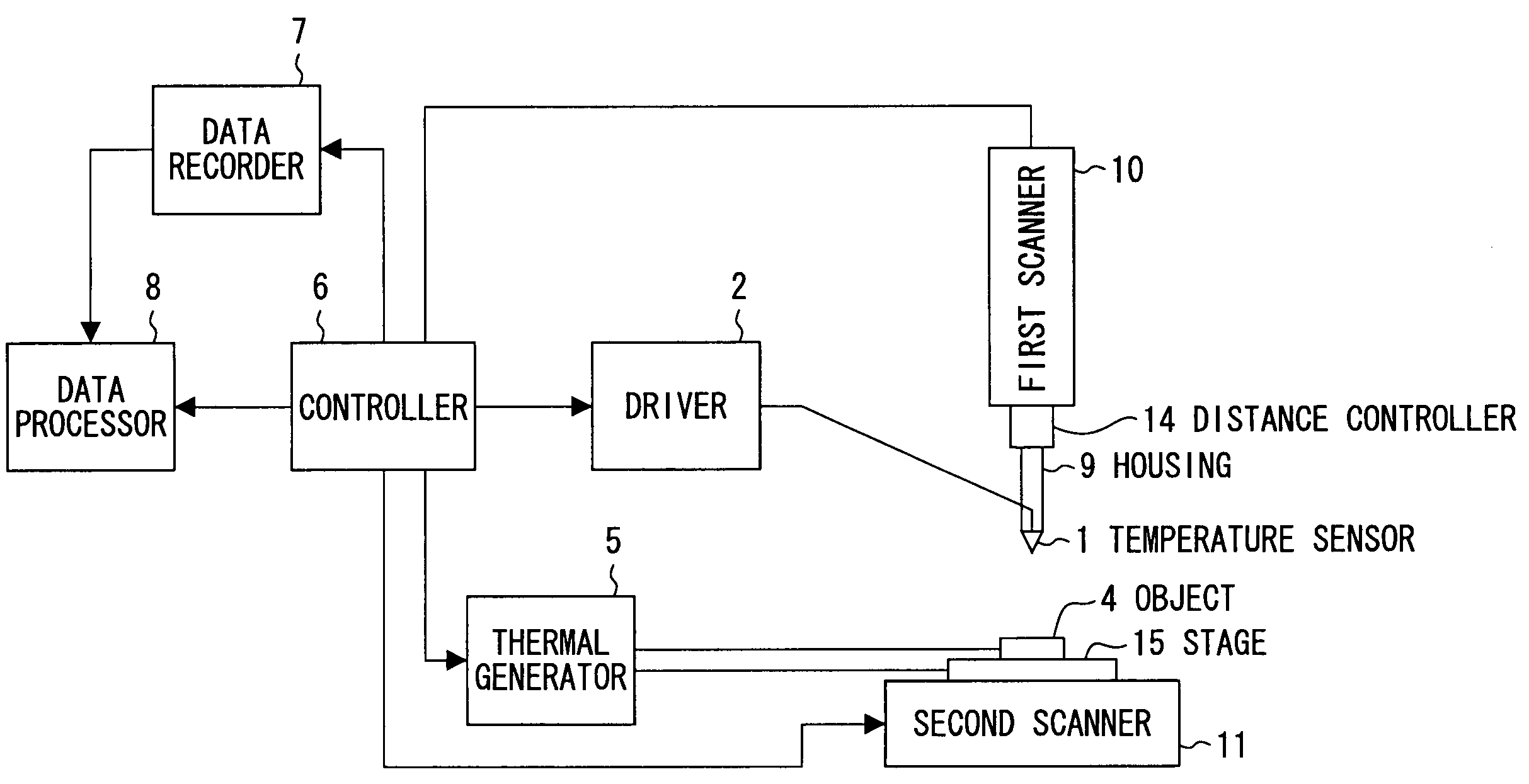
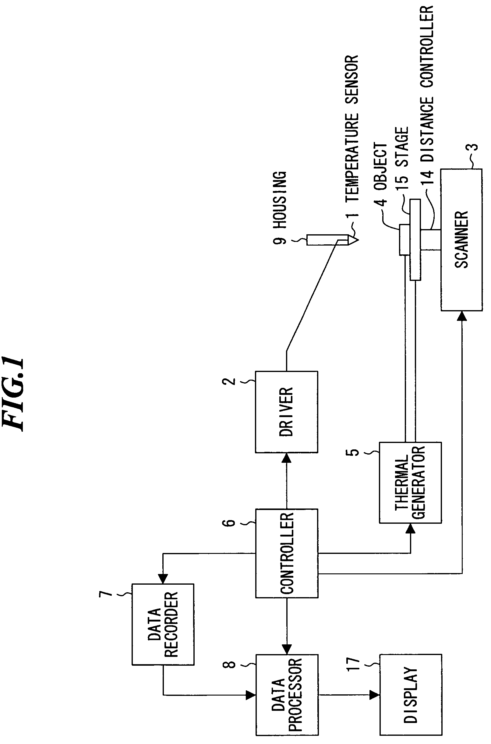
[0075]FIG. 1 shows the schematic representation of a global of thermal property measurement apparatus, related to the first conduct form of the present invention. For this conduct form, the object 4 is put on the stage 15. To measure the temperature in the object 4, the temperature sensor is positioned such that it faces to the object 4. The temperature sensor 1 is hold by the housing 9 and is driven by the driver 2. Thus, the temperature detector is composed of the temperature sensor and driver 2.

[0076]For this conduct form, to noncontactly and remotely measure the temperature of the target 4, an infrared temperature sensor is used as the sensor 1.

[0077]For the infrared temperature sensor, utilized is (a) simple infrared sensor using a various infrared element, (b) infrared sensor using infrared elements ...


PUM

PropertyMeasurementUnit
thermal propertyaaaaaaaaaa
temperatureaaaaaaaaaa
thermal conductivityaaaaaaaaaa

Abstract

A thermal property measurement apparatus capable of directly measuring thermal conductivity distribution in a ROI within a target only by measuring the temperature distribution that already exists in the ROI without generating other temperature fields artificially. The thermal property measurement apparatus includes a temperature detector for measuring temperatures at plural positions in the ROI, a distance controller for controlling a distance between the temperature detector and the target, a scanner for changing a relative position therebetween, a stage for putting the object thereon, a recorder for recording measured temperature data, position data and time data, a determination unit for determining whether at least one of thermal conductive phenomena and convection phenomena is dealt with or not, a processor for calculating thermal conductivity distribution in the ROI from the recorded data and temporal changeable references of the thermal conductivity in the ROI, and a controller.

Description

BACKGROUND OF THE INVENTION[0001]1. Field of the Invention[0002]The present invention relates to the method and apparatus for thermal property estimation (thermal properties measurement) particularly, using noncontactly measured temperatures for objects or living things.[0003]2. Description of a Related Art[0004]FIG. 5 shows the general thermal property estimation apparatus. In this apparatus, temperature distributions are generated in the object 4 by thermal source 13, and the generated temperatures at the plural positions are measured using the temperature detector 12 (thermocoupler etc). Then, by data processor 16, the generated heat fluxes are modeled using the finite difference method or finite element method, and the internal thermal conductivity distribution in an ROI (region of interest) is estimated using sensitivity theorem. Here, the ROI is the target region of unknown conductivity.[0005]However, this apparatus requires the external thermal sources for realizing the tempe...

Claims


Application Information

Patent Timeline
Patent Type & Authority Patents(United States)
IPC IPC(8): G01K3/08G01N25/18G01N25/20G06F17/10G06F17/13
CPCG01N25/18
Inventor SUMI, CHIKAYOSHI
Owner CHIKAYOSHI SUMI
Why Eureka
Try Eureka