Wave energy accumulator

a wave energy and accumulator technology, applied in the direction of sea energy generation, engine working fluid, coupling, etc., can solve the problems of inability to meet the minimum wave amplitude is relatively high, and the depletion rate is not acceptabl

Active Publication Date: 2010-04-06
SIEBER JOE +1
View PDF36 Cites 14 Cited by
  • Summary
  • Abstract
  • Description
  • Claims
  • Application Information

AI Technical Summary

Benefits of technology

[0019]According to one aspect of the invention, there is provided a fluid pressurization unit for compressing a fluid in response to natural wave action on a body of water such as an ocean. This device comprises a floating component and a slidably coupled piston assembly. The floating component has sufficient buoyancy to float on water waves and has a compression chamber with an inlet valve biased to receive a fluid at an intake pressure. The piston assembly is slidable within the compression chamber and has a piston shaft and a hollow piston head attached to the piston shaft. Inside the piston head is a piston reservoir with an inlet valve in communication with the compression chamber and biased to receive the fluid at an output pressure. The piston reservoir also has an outlet for discharging fluid pressurized to at least the output pressure from the pressurization unit. The piston assembly is fixable in place relative to the floating component such that relative movement between the floating component and piston assembly compresses fluid from the intake pressure to at least the output pressure. The piston reservoir has a volume that contains enough fluid at or above the output pressure that the fluid is discharged from the pressurization unit during both compression and expansion strokes of the piston assembly. This results in a unit that has a smoother delivery of pressurized fluid than a unit that discharges fluid only during the compression stroke.
[0020]The piston shaft can be hollow and contain a fluid intake conduit fluidly coupled to the compression chamber inlet valve, and a fluid discharge conduit fluidly coupled to the piston reservoir outlet. By locating these conduits in the piston shaft, any imbalance or drag caused by conduits attached laterally to the pressurization unit can be avoided.
[0025]The system also comprises at least one intermediate reservoir fluidly coupled between two stages by fluid conduits, for accumulating pressurized fluid from an upstream stage and to provide gas for a downstream stage; each intermediate reservoir is positioned between the stages to reduce fluid pressure transmission losses.

Problems solved by technology

These methods have associated environmental problems and in the case of fossil fuels, an unacceptable depletion rate.
Conventional single unit devices and multiple arrays of units conventionally connected in parallel suffer from the disadvantage that a relatively high minimum amplitude of wave must be encountered before the pressure in the cylinder reaches a level at which useable pressurized fluid is generated.
The minimum amplitude is determined by the design of the air compressing cylinder, and this disadvantage is present in both single unit devices and multiple unit arrays of the conventional methods and devices.
This design choice is of little practical value because with compressed gases of lower pressure, higher volumes must be conducted and low pressure gases are of lesser value in driving turbines.
The conventional parallel arrays of compression units do not address this disadvantage and the total volume of energy captured is increased only by increasing the number of compression units.
This solution is not cost effective given the capital cost of building an array of units and the operational cost of maintaining them.

Method used


Image

  • Wave energy accumulator
  • Wave energy accumulator
  • Wave energy accumulator

Examples


Embodiment Construction

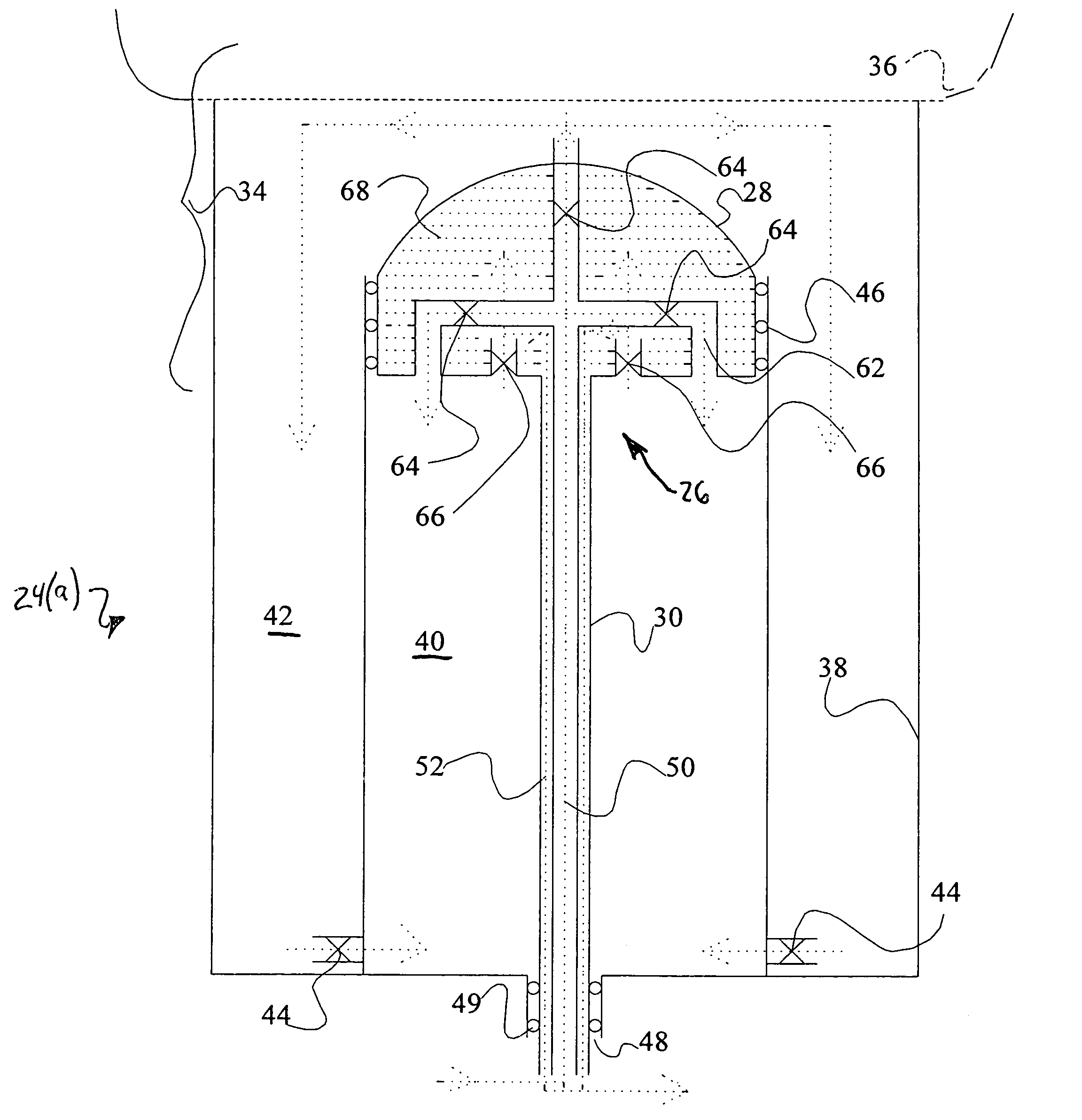
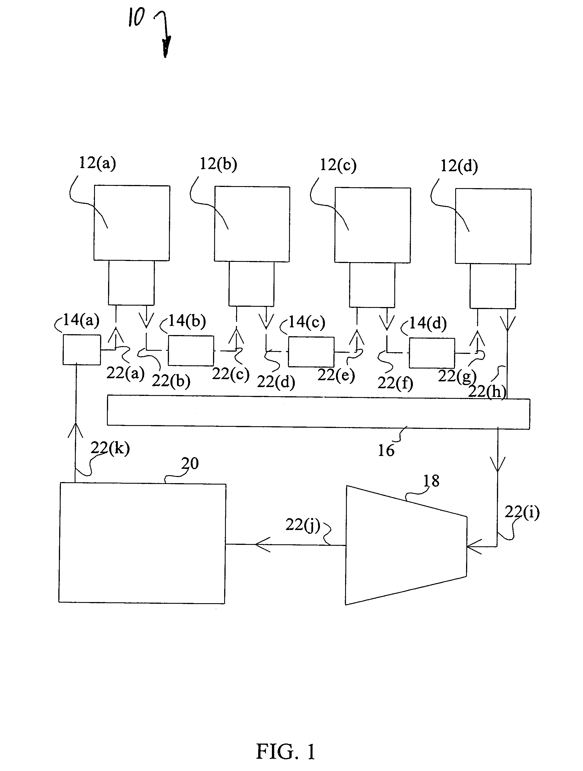
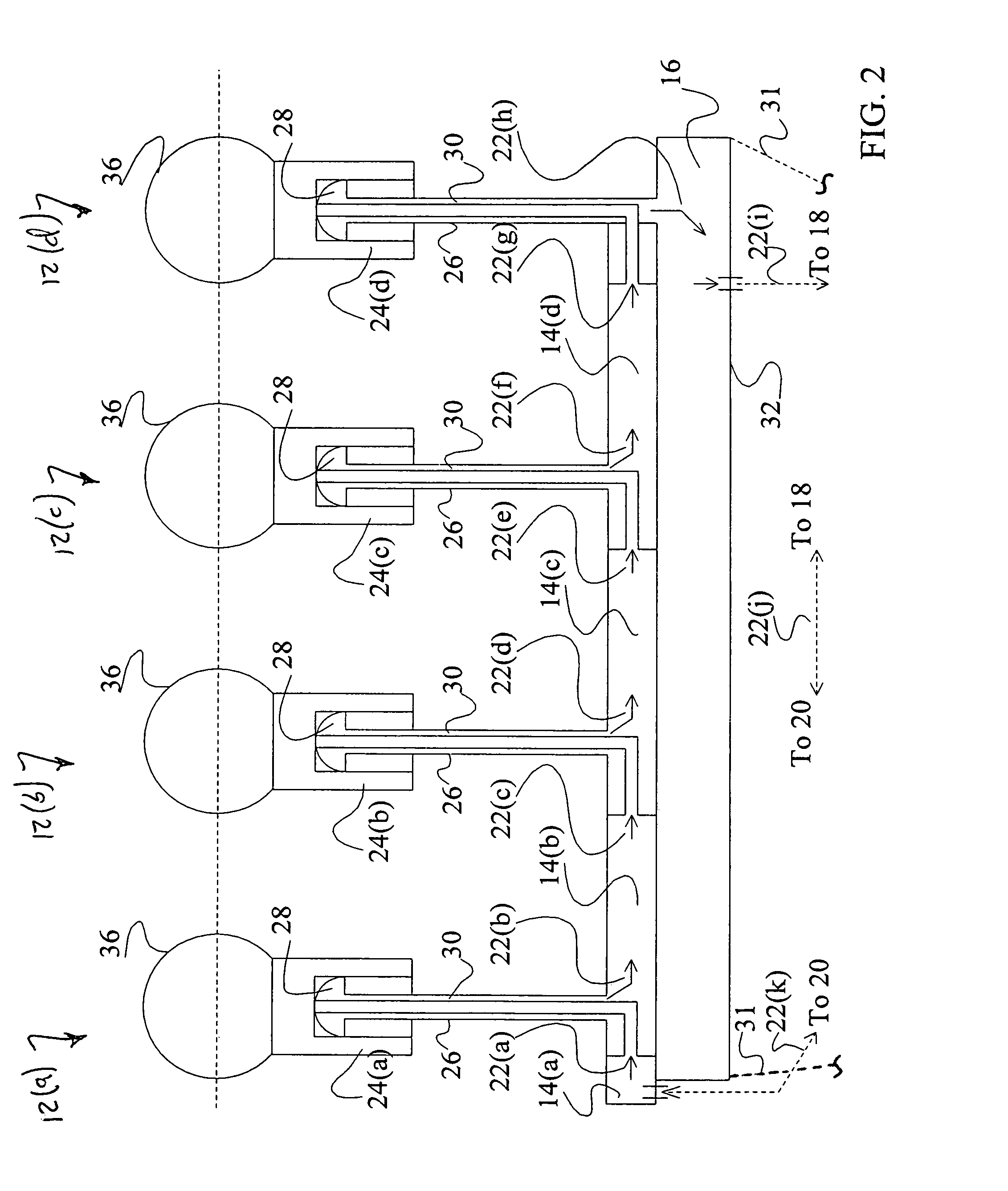
[0038]Referring to FIG. 1, and according to a first embodiment of the invention, a wave energy accumulator system 10 converts energy of water waves into potential energy for performing useful work, e.g. by generating electrical energy, and / or directly into useful work.

[0039]The system 10 comprises multiple pressurization stages 12(a)-(d), intermediate reservoirs 14(a)-(d), a high pressure reservoir 16, a turbine 18 and electric generator assembly and a low pressure reservoir 20 all of which are fluidly interconnected by fluid flow conduits 22(a)-(k) to form a closed fluid loop system. A compression fluid is circulated through this system 10, is pressurized by the pressurization stages 12(a)-(d), and is used to power the turbine 18 which is used to generate electric power.

[0040]Instead of a closed loop system, the compression fluid may be input at the initial pressurization stage 12(a) and exhausted after exiting the turbine 18 if desired (not shown). Also, the number of pressurizati...


PUM


Abstract

A fluid pressurization unit compresses a fluid in response to natural wave action on a body of water such as an ocean. The unit comprises a floating component and a piston assembly. The floating component has sufficient buoyancy to float on water waves and has a compression chamber with an inlet valve biased to receive a fluid at an intake pressure. The piston assembly is slidable within the compression chamber and has a piston shaft and a hollow piston head attached to the piston shaft, which defines a piston reservoir therein with an inlet valve in communication with the compression chamber and biased to receive the fluid at an output pressure, and an outlet for discharging fluid pressurized to at least the output pressure from the pressurization unit. The piston assembly is fixable in place relative to the floating component such that relative movement between the floating component and piston assembly compresses fluid from the intake pressure to at least the output pressure.

Description

BACKGROUND OF THE INVENTION[0001]1. Field of the Invention[0002]The invention described herein relates to accumulating wave energy, and in particular, to a method and apparatus for converting energy in water waves into potential energy for performing useful work and / or directly into useful work.[0003]2. Description of the Related Art[0004]Electrical energy for general use is being generated primarily by natural water flow, by burning fossil fuels and by nuclear generation. These methods have associated environmental problems and in the case of fossil fuels, an unacceptable depletion rate. This has led researchers to investigate the possibilities of harnessing energy from wave action and from wind.[0005]A great variety of approaches have been proposed to generate energy from waves. One common approach is to utilize a float which rides up and down with wave motion guided by a fixed or anchored member which remains relatively stationary. An air compression cylinder is introduced betwee...

Claims


Application Information

Patent Timeline
Patent Type & Authority Patents(United States)
IPC IPC(8): F04B35/00F04F99/00
CPCF03B13/187F03B13/24F04B35/004F04B17/00Y02E10/38F05B2210/18Y02E10/30F03B13/1875
Inventor SIEBER, JOE
Owner SIEBER JOE
Why Eureka
Try Eureka