High strength substructure reinforcement for crowns and bridges

a high-strength, bridge-like technology, applied in the field of prosthodontic systems, methods and apparatuses, can solve the problems of fracturing of veneered porcelain while the ceramic core remains intact, more unsupported buccal porcelain, and still large bulks of unsupported porcelain, and achieves high-strength substructure, high-strength substructure, and reinforced substructure

Inactive Publication Date: 2010-04-06
ZIRCORE
View PDF16 Cites 8 Cited by
  • Summary
  • Abstract
  • Description
  • Claims
  • Application Information

AI Technical Summary

Benefits of technology

[0008]An object of the present invention is to provide a high strength substructure for prosthodontics, such as crowns and bridges. Another object of the present invention is to provide a process for manufacturing prosthodontics having a high strength substructure. Yet another object of the instant invention is to provide a substructure reinforcement for prosthodontic substructures. Still another object of the instant invention is to provide a process for manufacturing prosthodontics having a reinforced substructure. Another object of the instant invention is to provide a strengthening mechanism for prosthodontic substructures close to the region where the stress is being applied to the structure. Another object of the instant invention is to provide a prosthodontic substructure that is aesthetically pleasing and which is relatively simple to design and construct.
[0010]In a preferred embodiment, the reinforcement structure of the instant invention is incorporated into the CAD-CAM design stage for a high-strength, milled substructure. The design of this reinforcement structure depends on the software associated with each CAD-CAM system. The reinforcement structure may be designed primarily manually using conventional CAD-CAM design software, which allows a user to place pre-made shapes down over an image on the screen, increase or decrease the existing shape, distort the shape in one / multiple vanishing points, increase the volume of the shape from a point-angle or free hand-paint an area. In one preferred embodiment, the reinforcement structure of the instant invention is designed primarily automatically by a CAD-CAM (or other software) application that includes a pull down annular shape that is placed around the concentric image being made over the die from a library of tools in the software palate. The annular shape may be enlarged (or reduced) in x, y, and z axis as necessary to bulk-up (or down) the core being designed. In another preferred embodiment, the reinforcement structure of the instant invention is designed primarily automatically by a CAD-CAM (or other software) application by the operator pulling the structure from a point, line, cluster of points, etc., to distort a portion of the shape of the main body of the substructure to create the reinforcement structure without distorting the overall shape of the main body. In yet another preferred embodiment, the reinforcement structure of the instant invention is pre-designed into the main body of the substructure. In such an embodiment, a basic shape for the main body of the substructure is selected from a library of shapes available in the software application based upon the desired shape for the final restoration, with the reinforcement structure already built into the shape of the main body. The operator then either pushes, pulls, takes away or otherwise erases portions of the pre-designed shape of the main body (including the reinforcement structure) to meet the needs for the specific restoration. In still another preferred embodiment, the substructure (including the reinforcement structure of the instant invention) is designed by first obtaining the desired shape for the restoration and then subtracting away or deconstructing from that shape to leave the substructure shape. In such an embodiment, the part of the final shape that is subtracted is determined to maximize the aesthetic appearance of the final restoration by concealing the substructure.
[0011]In one embodiment the reinforcement structure is over-built in the CAD-CAM design phase on a relatively freehand basis (or through use of the automatic software discussed above), preferably at the crest of the preparation, and protruding about 2 mm out from the base coping. After milling is completed, the contact regions are adjusted, and the amount of the lingual and labial prominence is modified as desired, by hand. If necessary or desired, the reinforcement structure is thinned out after milling. There is little requirement for bulk of the reinforcement structure because the high-strength non-metal substructure of the instant invention is not only strong, it is also very rigid. The final frame design is easy to design, construct and manage.
[0012]The aesthetic appearance of the piece is increased by reducing the potential for the sub-structure to “Shine-Through” the surface of the final restoration at the mesio-buccal region. To minimize Shine-Through, the prominent sub-structure may be reduced through the crown contour. Veneering porcelain is then applied over the deficiency. In addition, the reinforcement structure may be masked when the final restorations are characterized.
[0013]The reinforcement structure of the instant invention has the advantage that the marginal display of opaque porcelain from the underlying high strength core can be minimized, because there is no need for a heavy bulky collar to gain strength or to provide support. The normal thickness of the base coping can be extended to the margin. This is particularly useful in implant based units, where there tends to be a bigger build out from a relatively narrow base.
[0015]The reinforcement support of the instant invention is remarkably simple to incorporate and use in practice. In one embodiment of the instant invention, for single unit restorations, a thin layer coping is designed over the preparation (such as a pre-manufactured implant abutment, a custom manufactured implant abutment, prepared portion of tooth on which restorations is supported, etc.) with a relatively crude shaping of the reinforcement structure. In the preferred embodiment, the inventive reinforcement structure is established at the height of the contact point and parallels the occlusal plane. When the reinforcement structure has been established relatively crudely in the design stage, it can then be refined quickly once the unit is positioned on a master model.

Problems solved by technology

Notwithstanding the impressive strengths of these substructure materials, these figures are deceptive due to the more limited strength of the veneering materials used for the crowns and / or bridges.
Furthermore, the more aesthetic and much weaker veneering materials are not adequately supported by the higher strength ceramic core, often resulting in fracturing of the veneering porcelain while the ceramic core remains intact.
First, implants tend to be placed more lingually than the teeth they are replacing, which often results in more unsupported buccal porcelain.
Second, the diameter of an implant platform is often smaller than the tooth it is replacing, giving rise to still bigger bulks of unsupported porcelain.
The situation is further complicated by implants being more rigid than teeth, while at the same time resulting in reduced proprioceptive capabilities.
Nevertheless, bulking up the substructure often results in a less desirable aesthetic appearance, as the substructure becomes more visible through the veneer.
Notwithstanding, these design elements are not much help in strengthening the most visible portions of the teeth, the buccal surfaces.
This can be a particular problem in the mandible because in a normally related occlusion, the buccal cusps of the mandibular teeth serve as occlusal supports.
Using a high strength ceramic substructure, which tends to be opaque and of high luminosity, half way up the buccal surface to reinforce the veneer porcelain of the cusp is just as unacceptable as using a metal frame in the same manner.

Method used


Image

  • High strength substructure reinforcement for crowns and bridges
  • High strength substructure reinforcement for crowns and bridges

Examples


Embodiment Construction

[0022]As required, a detailed embodiment of the present invention is disclosed herein; however, it is to be understood that the disclosed embodiment is merely exemplary of the principles of the invention, which may be embodied in various forms. Therefore, specific structural and functional details disclosed herein are not to be interpreted as limiting, but merely as a basis for the claims and as a representative basis for teaching one skilled in the art to variously employ the present invention in virtually any appropriately detailed structure.

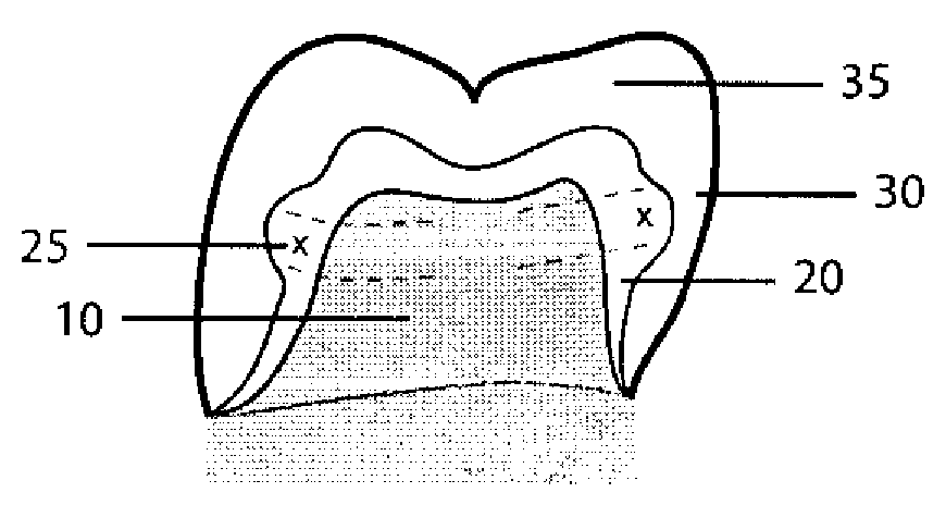
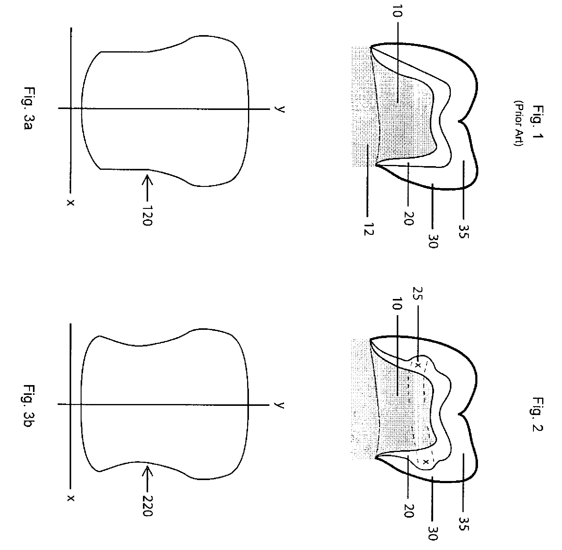
[0023]Referring to FIG. 1, a dental implant including a conventional substructure is shown. As is shown in FIG. 1, the implant includes abutment portion 10 over which thin coping 20 is fit. Crown 30 is formed about coping 10 from a veneer porcelain to the shape of the final restoration. As can be seen in FIG. 1, a considerable amount of bulking out of the veneer porcelain is required to establish the final form of the restoration. The stresses...


PUM


Abstract

A reinforcement for a dental restoration substructure is provided. The reinforcement is a generally annular structure that protrudes from the body of the substructure generally near an occlusal portion of the restoration. The annular structure provides a support for veneering porcelain at the location of the greatest thickness of the porcelain and at the location where occlusal stress is applied, and fractures of veneering porcelain are commonly experienced.

Description

FIELD OF THE INVENTION[0001]The present invention relates generally to prosthodontic systems, methods and apparatuses. More particularly, the present invention is concerned with a high strength substructure for crowns and bridges and a process for manufacturing dental crowns and bridges having a high strength substructure.BACKGROUND OF THE INVENTION[0002]For some time, dental prostheses were produced from porcelain veneering material bonded onto a metal framework (substructure, or core). This porcelain-fused-to-metal (“ceramo metal”) construction required a fairly bulbous metal core, with a fairly uniform porcelain thickness to avoid de-lamination under sheer conditions. More recently, dentists have been offered high strength ceramic materials as substitutes for the conventionally metal substructures in ceramo-metal crowns and / or bridges. These porcelain veneer fused to non-metal core crowns / bridges offer reduced labor costs, equivalent or superior precision to ceramo-metal alternat...

Claims


Application Information

Patent Timeline
Patent Type & Authority Patents(United States)
IPC IPC(8): A61C5/08
CPCA61C5/002A61C13/0004A61C5/10A61C13/0022A61C5/20A61C5/77
Inventor HUNT, PETER R.SAGER, ROBERT D.
Owner ZIRCORE
Why Eureka
Try Eureka