Crystal oscillator

a crystal oscillator and crystal oscillator technology, applied in oscillator generators, pulse techniques, instruments, etc., can solve the problems of oscillation output level drop and circuit loss increase, and achieve stable oscillation frequency, reduce apparent q value, and prevent oscillation frequency changes

Inactive Publication Date: 2010-04-06
NIHON DEMPA KOGYO CO LTD
View PDF6 Cites 8 Cited by
  • Summary
  • Abstract
  • Description
  • Claims
  • Application Information

AI Technical Summary

Benefits of technology

[0021]It is an object of the present invention to provide a crystal oscillator that is provided with a crystal resonator for reducing phase noise in the oscillation frequency and that prevents the occurrence of interruptions in oscillation caused by the difference between the oscillation frequency of the crystal oscillator and the resonant frequency of the crystal resonator.
[0023]In the present invention, a resistor which is connected in parallel to the crystal resonator reduces the resonance acutance (i.e., Q value) of the crystal resonator, or strictly speaking, reduces the resonance acutance of the parallel circuit of the crystal resonator and resistor, and broadens the pass bandwidth of the crystal resonator. The resistor that is here connected in parallel to the crystal resonator is referred to as a damping resistor.
[0025]Reducing the apparent Q value of the crystal resonator, i.e., the Q value of the parallel circuit of the crystal resonator and the damping resistor, enables a broadening of the apparent bandwidth in the resonant frequency of the crystal resonator. If the apparent Q value is reduced by the damping resistor, almost all of the fundamental wave component of this oscillation frequency can pass through the crystal resonator despite slight changes on the ppm (part-per-million) order of the oscillation frequency in the oscillation circuit. As a result, halts in oscillation are prevented and stable oscillation is maintained.
[0027]In the crystal oscillator of the present invention, a temperature compensation mechanism may be provided for compensating the frequency-temperature characteristic of the crystal unit. Providing a temperature compensation mechanism for the crystal unit prevents changes in the oscillation frequency caused by the frequency-temperature characteristic of the crystal unit and enables the supply of a stable oscillation frequency. In this case, changes in the ambient temperature will, due to the frequency-temperature characteristic of the crystal resonator, also cause changes on the order of several ppm in the resonant frequency of the crystal resonator, whereby the resonant frequency will diverge on the order of several ppm from the oscillation frequency in which temperature compensation is being implemented. In the present invention, a damping resistor is provided to reduce the apparent Q value of a crystal resonator and broaden the bandwidth, whereby the oscillation frequency component can pass the crystal resonator regardless of divergence between oscillation frequency and resonant frequency that accompanies changes in temperature. Accordingly, oscillation is continued at a temperature-compensated oscillation frequency. Compared to the configuration described in US 2005 / 0285690 A1, the present invention allows a simplification of the circuit configuration because, even when a temperature compensation mechanism is provided in the configuration of the present invention, the temperature compensation mechanism need only be provided for the crystal unit.

Problems solved by technology

It should be noted that the Q value can be reduced even if a resistor is serially connected to the crystal resonator, but this approach is not expedient because in such cases, the equivalent resistance of the crystal resonator is substantially larger, whereby the circuit loss increases and the oscillation output level drops.

Method used


Image

  • Crystal oscillator
  • Crystal oscillator
  • Crystal oscillator

Examples


Embodiment Construction

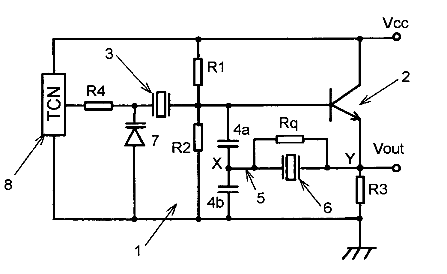
[0036]In FIG. 4, which shows a quartz crystal oscillator according to a preferable embodiment of the present invention, the same reference numerals are given to constituent elements that are identical to elements in FIG. 1, and redundant explanation of these elements is here omitted.

[0037]As with the crystal oscillator shown in FIG. 1, the crystal oscillator shown in FIG. 4 is provided with: resonance circuit 1 that is made up from quartz crystal unit 3 and split capacitors 4a and 4b; oscillation transistor Q for feeding back and amplifying the oscillation frequency component; and quartz crystal resonator 6 inserted in output line 5. In the circuit shown in FIG. 4, damping resistor Rq is provided in parallel to crystal resonator 6, and temperature compensation is realized for crystal unit 3 by a temperature compensation mechanism of the indirect type. In the circuit shown in FIG. 4, moreover, the collector of transistor Q is directly connected to power supply Vcc without the provisi...


PUM


Abstract

A crystal oscillator in which phase noise is reduced includes: a resonance circuit having a crystal unit and split capacitors connected to the crystal unit; a transistor for oscillation having a base connected to the connection node of the crystal unit and the split capacitors; an output line for connecting the node for connecting together the split capacitors and the emitter of the transistor; a crystal resonator inserted in the output line; and a resistor connected in parallel to the crystal resonator.

Description

[0001]This Application is a U.S. Nonprovisional Utility Patent Application which claims foreign priority from Japanese Application No. 2005-229079, filed Aug. 8, 2005, the complete disclosure of which is incorporated herein by reference.BACKGROUND OF THE INVENTION[0002]1. Field of the Invention[0003]The present invention relates to a quartz crystal oscillator in which phase noise is reduced by inserting a crystal resonator in a feedback loop of an amplifier for oscillation, and more particularly to a crystal oscillator that reliably maintains oscillation.[0004]2. Description of the Related Art[0005]Crystal oscillators feature a high degree of stability of oscillation frequency and are therefore frequently used in high-performance radio equipment. In these crystal oscillators, Japanese Patent Laid-open Application No. 9-153740 (JP-A-H9-153740), for example, discloses a crystal oscillator in which a crystal resonator is arranged in the output portion of an oscillation circuit separate...

Claims


Application Information

Patent Timeline
Patent Type & Authority Patents(United States)
IPC IPC(8): H03B5/32
CPCH03B5/368H03L1/028H03L1/023H03L1/022
Inventor HASHIMOTO, HIDEO
Owner NIHON DEMPA KOGYO CO LTD
Why Eureka
Try Eureka