
Error detection in physical interfaces for point-to-point communications between integrated circuits

a physical interface and integrated circuit technology, applied in the direction of coding, instruments, code conversion, etc., can solve the problems of thwarting reliable point-to-point communication, and conventional serial data links are susceptible to data corruption during transit, so as to reduce the time the apparatus receives.

Active Publication Date: 2010-04-06
LATTICE SEMICON CORP
View PDF5 Cites 86 Cited by
  • Summary
  • Abstract
  • Description
  • Claims
  • Application Information

AI Technical Summary

Benefits of technology

This patent is about a way to make sure that data is sent reliably between electronic devices. It uses a special interface that can detect errors in the data as it is being sent over a physical medium. This helps to make sure that the data is sent correctly. This invention is particularly useful for sending data bits using low-amplitude, high-frequency signaling.

Problems solved by technology

But with traditional physical interfaces both transmitting data bits at faster data rates and at decreasing amplitudes (i.e., decreasing transmission power), the effects of background noise on the strength of the data signals causes the signal-to-noise ratios to decrease, which is indicative of an increase in errors that could thwart reliable point-to-point communications.
While conventional physical interfaces that provide for serial data communications reduce both noise and power, at least one drawback is that conventional serial data links are susceptible to data corruption during transit.
While functional, the data link layer performs these error detection and correction processes beyond the physical interface, thereby delaying error detection and / or resolution.
Also, conventional physical interfaces are generally not well suited to facilitate error detection and correction in a standardized manner.
As such, they can not readily be adapted to provide timely and reliable data transfers for asynchronous and serial data communications, such as over a serial data link.
Further, conventional physical interfaces are not generally conducive to at least provide: (1) transparent error detection and recovery techniques that do not require an application to participate in specialized error handling techniques, and (2) efficient transmissions of error detection codes to increase the rate that those codes are transferred over the serial data link.

Method used


Image

  • Error detection in physical interfaces for point-to-point communications between integrated circuits
  • Error detection in physical interfaces for point-to-point communications between integrated circuits
  • Error detection in physical interfaces for point-to-point communications between integrated circuits

Examples


Embodiment Construction

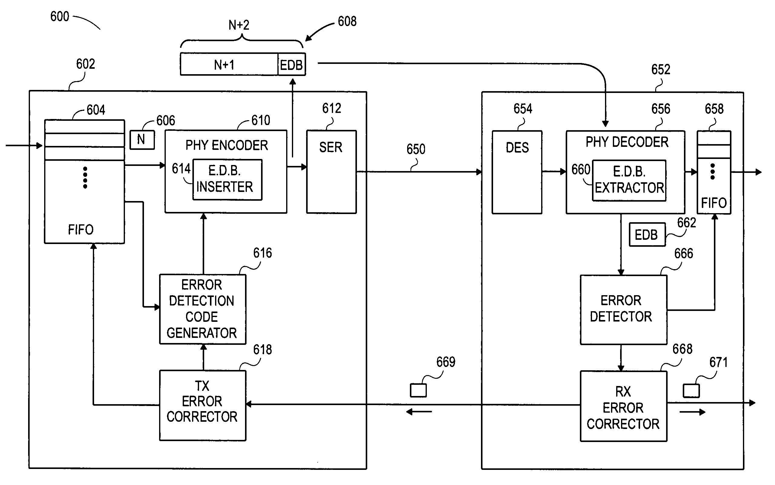
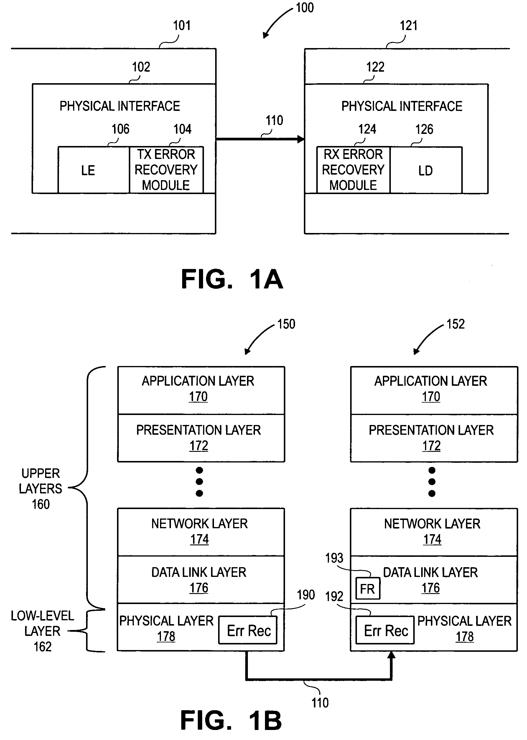
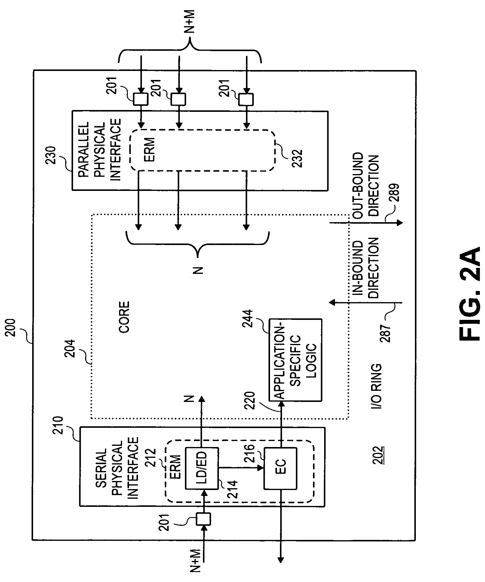
[0024]FIG. 1A is a block diagram 100 illustrating physical interfaces that include error recovery modules to detect errors in association with line encoding / decoding, according to at least one specific embodiment of the invention. Physical interfaces 102 and 122 provide for physical connectivity between devices 101 and 121, each of which can be an integrated circuit, such as a memory chip, or an electronic device, such as an Ethernet line card or a networked computer. Physical interfaces 102 and 122 include a line encoder (“LE”) 106 and a line decoder (“LD”) 126, respectively, to facilitate transmission and receipt of data bits via physical medium 110. In one embodiment, line encoder (“LE”) 106 performs line encoding (also referred to as “line coding”), which is the translation of digital information expressed in binary (i.e., data bits) into a specific code (or code word) to optimize transmission of the encoded data bits over a particular type of medium, such as copper wire, optica...


PUM


Abstract

An apparatus, system and method for detecting errors in a physical interface during the transmission and / or receipt of data communications between integrated circuits (“ICs”) are disclosed. In one embodiment, an apparatus is configured to operate as or within a receiving physical interface. The apparatus includes a decoder configured to decode a subset of encoded data bits to yield decoded data bits. It also includes a physical interface (“PI”) error detection bit extractor configured to extract a physical interface error detection bit from the decoded data bits. As such, the apparatus uses the physical interface error detection bit to determine whether the encoded data bits include at least one erroneous data bit as an error. In some embodiments, the apparatus includes an error detector configured to operate within a physical layer. In at least one embodiment, the apparatus efficiently transmits error detection codes within, for example, an NB / (N+1)B line coder.

Description

BRIEF DESCRIPTION OF THE INVENTION[0001]This invention relates generally to an apparatus and method for providing reliable data communications between electronic devices, and more particularly, to a physical interface configured to efficiently detect errors at the physical interface during point-to-point transmission of data bits over a physical medium between electronic devices. In one embodiment, the point-to-point transmission of data bits employs low-amplitude, high-frequency signaling along a serial data link.BACKGROUND OF THE INVENTION[0002]Point-to-point communication between electronic devices, such as integrated circuits (“ICs”), is generally considered to be reliable, especially when a dedicated synchronous clock line is used to synchronize data transfers. In particular, many system designers expect communications between ICs to conform to a prevailing assumption that data bits exchanged between ICs are the same data bits. For example, most conventional processor ICs are d...

Claims


Application Information

Patent Timeline
Patent Type & Authority Patents(United States)
IPC IPC(8): H03M13/00
CPCH04L1/0045H04L25/4908H04L1/0061H04L2001/0092H04L1/00H04L69/32H04L9/40
Inventor SCHMIDT, BRIAN K.BUTCHER, LAWRENCE LLEWELYN
Owner LATTICE SEMICON CORP
Learn More