Method for eliminating sources of error in the system correction of a coordinate measuring machine

a technology of coordinate measuring machine and system correction, which is applied in the direction of large fixed members, using electrical/magnetic means, and large fixed members, etc., can solve the problems of error in the measurement of the measurement values used, and it is not possible to determine error components that provide the same distortion in all individual measurements, so as to achieve the effect of eliminating the source of error in the system correction of the coordinate measuring machin

Active Publication Date: 2010-04-13
VISTEC SEMICON SYST
View PDF12 Cites 9 Cited by
  • Summary
  • Abstract
  • Description
  • Claims
  • Application Information

AI Technical Summary

Benefits of technology

[0011]It is therefore an object of the present invention to provide a method with which sources o

Problems solved by technology

The cause has been identified as being errors in the measuring of the measurement values used for correction determination.
Based on the teaching

Method used


Image

  • Method for eliminating sources of error in the system correction of a coordinate measuring machine
  • Method for eliminating sources of error in the system correction of a coordinate measuring machine
  • Method for eliminating sources of error in the system correction of a coordinate measuring machine

Examples


Embodiment Construction

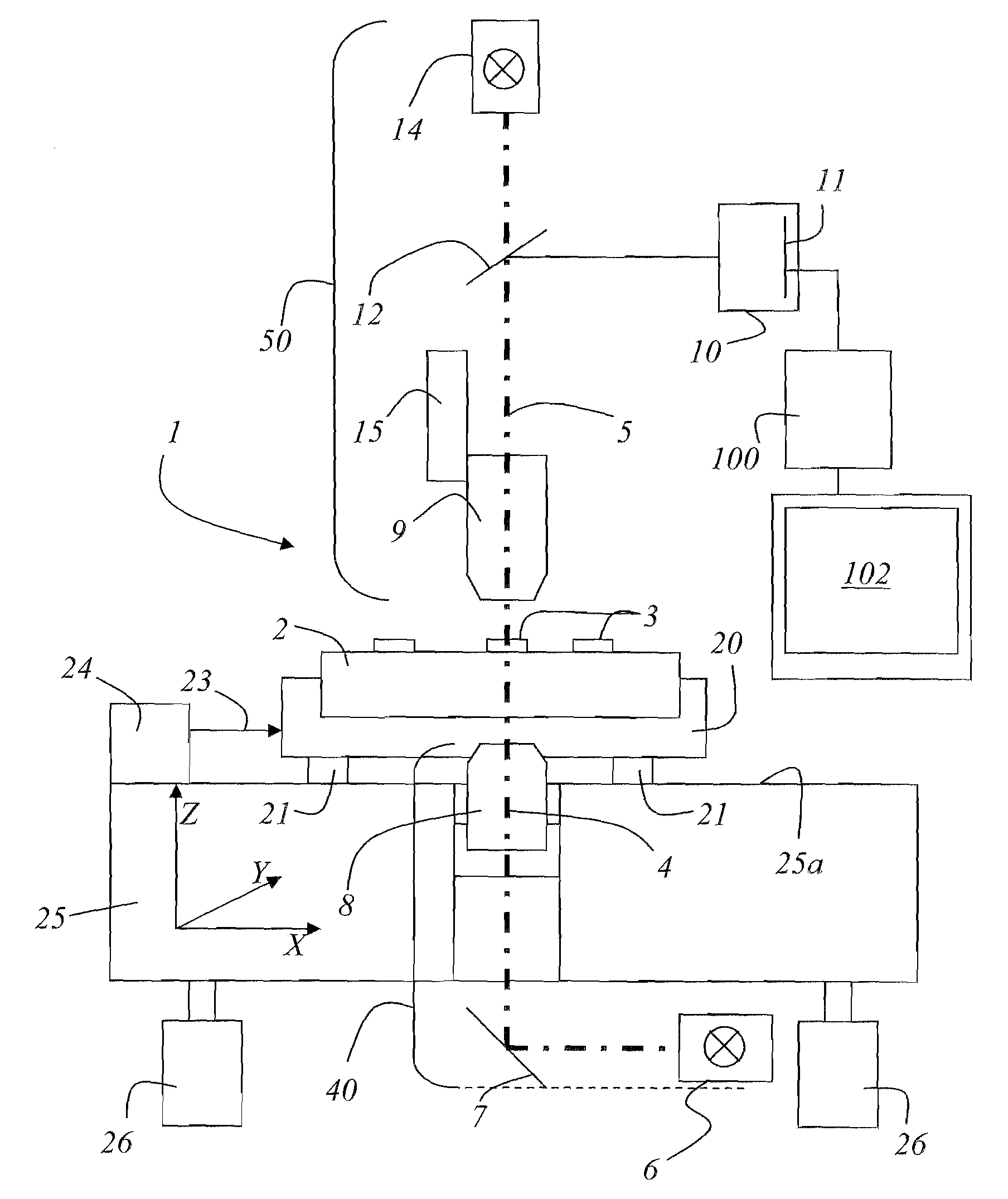
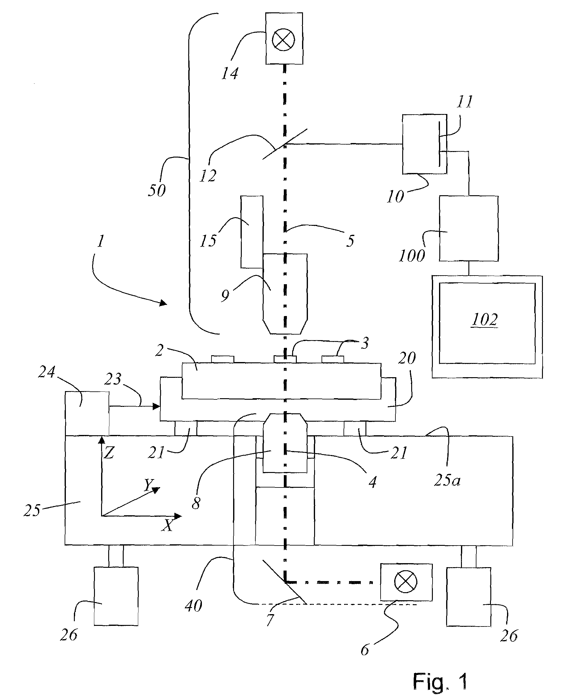
[0034]FIG. 1 shows a schematic representation of a coordinate measuring machine as has long been known from the prior art. In the description that follows, the coordinate measuring machine is referred to as the “device”. It should also be noted that in the description that follows and in the drawings, the same elements are denoted with the same reference signs.

[0035]The device 1 comprises a measuring table 20, which is arranged displaceable on air bearings 21 in the X-coordinate direction and in the Y-coordinate direction in a plane 25a. Other bearings than the air bearings can also be used for the mounting of the measuring table 20. The plane 25a is formed from one element 25. In a preferred embodiment, the element 25 is made from granite. However, it is obvious to a person skilled in the art that the element 25 can also be made from another material which makes a precise plane available for the displacement of the measuring table 20. The position of the measuring table is measured...


PUM


Abstract

A method is disclosed for eliminating sources of error in the system correction of a coordinate measuring machine. Herein, a number j of reference structures 33 on a rigid reference object 30 are measured in a starting orientation k=0, and the starting coordinates and the reference coordinates of the reference structures 33 on the reference object 30 are determined in a number k≧3 of mutually different orientations.

Description

RELATED APPLICATIONS[0001]This application claims priority to German Patent Application No. 10 2007 009 591.2, filed on Feb. 26, 2007, and German Patent Application No. 10 2007 000 999.4, filed on Dec. 5, 2007, and claims the benefit under 35 USC 119(e) of U.S. Provisional Application No. 60 / 891,581, filed on Feb. 26, 2007, all of which are incorporated herein by reference in their entirety.BACKGROUND OF THE INVENTION[0002]The present invention relates to a method for eliminating sources of error in the system correction of a coordinate measuring machine.[0003]In general, at least one illumination apparatus is provided for a coordinate measuring machine. Herein, for measuring the position of a structure on a substrate or object (mask for the semiconductor industry, or a wafer), at least one laser interferometer system is used for determining a positional displacement of the substrate or object in at least one spatial direction. The at least one laser interferometer system is accommo...

Claims


Application Information

Patent Timeline
IPC IPC(8): G01B5/004G01B21/04G06F19/00
CPCG01B21/045G01B11/03
Inventor HEIDEN, MICHAELRINN, KLAUS
Owner VISTEC SEMICON SYST
Why Eureka
Try Eureka