Hangerless precast cladding panel system

a precast cladding and hanging plate technology, applied in the direction of roof covering, walls, building components, etc., can solve the problems of leakage at roof-to-wall junctures, moisture infiltration behind the cladding, and can not be completely eliminated, so as to reduce the overall durability and value of the building

Inactive Publication Date: 2010-04-13
KUELKER PETER
View PDF26 Cites 14 Cited by
  • Summary
  • Abstract
  • Description
  • Claims
  • Application Information

AI Technical Summary

Benefits of technology

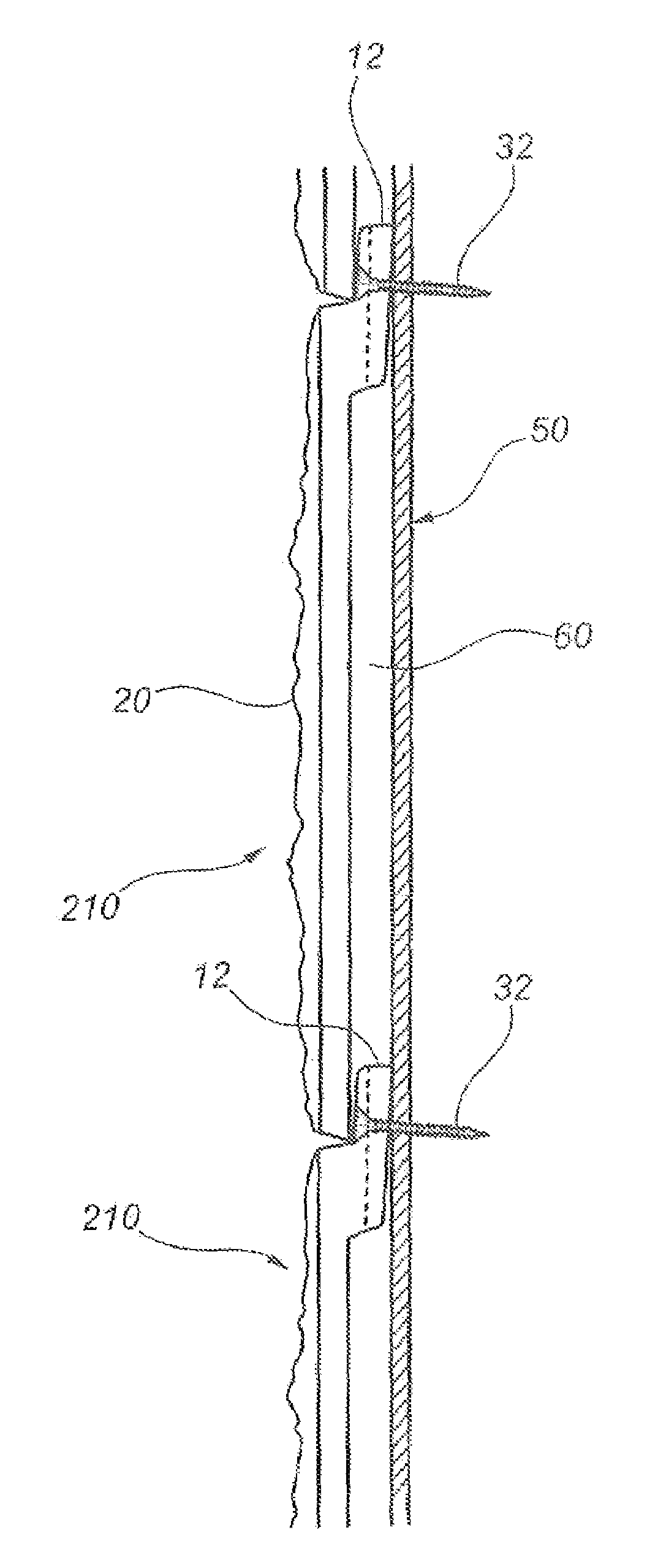
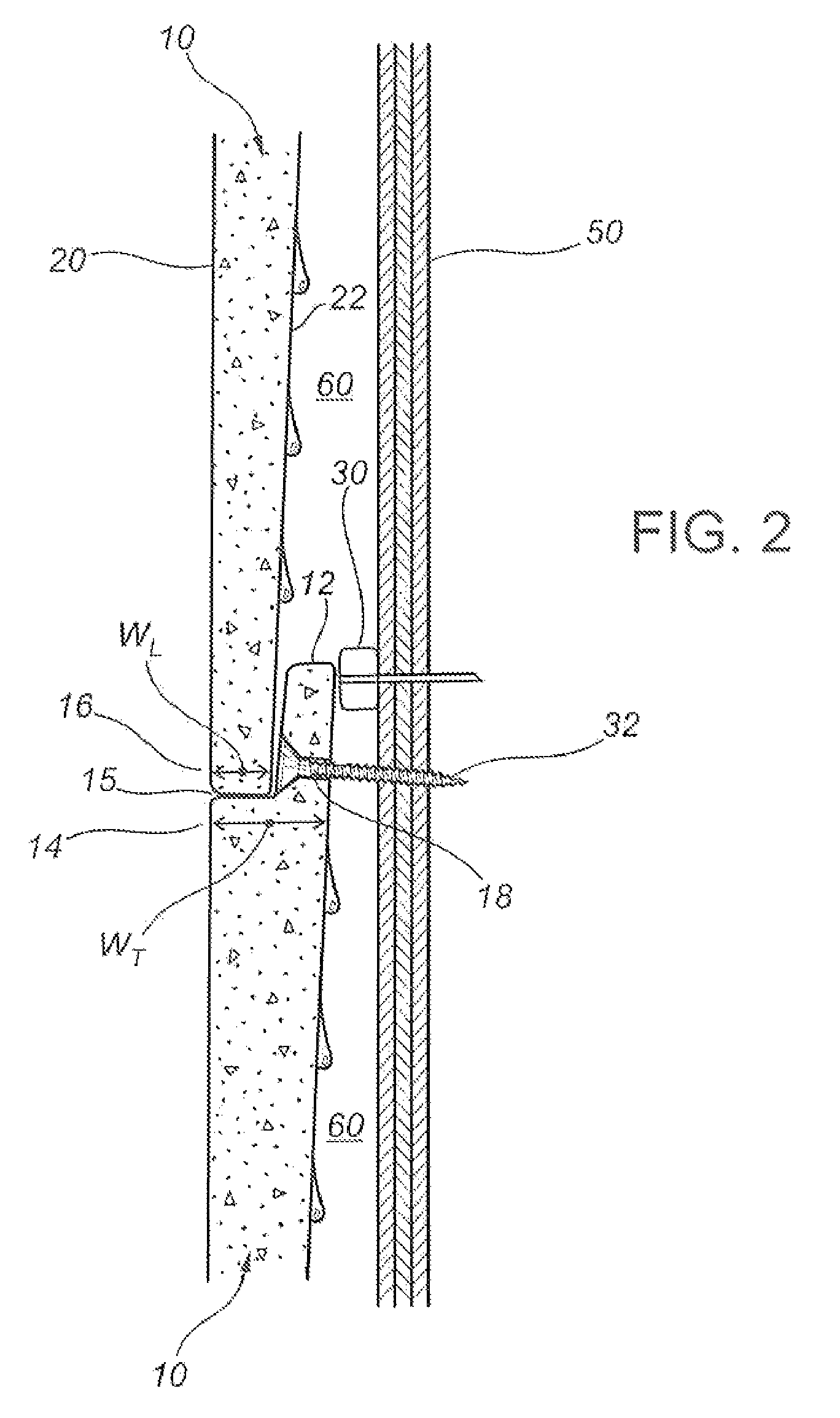
[0025]In preferred embodiments of the panel and the panel system, the horizontal ledge of the panel slopes transversely downward toward the front face of the panel, to enhance the efficiency of drainage of moisture down the rear faces of the panels and toward the front faces of the panels in lower edges of the rear faces of the panels.
[0035]In all of the embodiments described above, the centre of gravity of the panels will be in a position such that the lower edges of the panel will inherently tend to move toward the supporting structure to which they are being mounted. This is a desirable tendency since it helps to maintain the lower panels edges within the notches of the panels below or (as the case may be) against the lower spacer means. This desirable tendency is supplemented for panel embodiments having a tapering thickness (such that the rear face of the upstand is tapered or bevelled), since in these cases the installation of the fasteners mounting the panels to the supporting structure will tend to impart a rotational moment urging the lower panels edges toward the supporting structure. A similar effect may be provided for when using panels having substantially uniform thickness and rearwardly-protruding upstands, by bevelling the rear faces of the upstands.

Problems solved by technology

Although caulking or other sealant materials are typically used to seal the spaces between cladding panels, the possibility of moisture infiltration behind the cladding—as a result of vapour migration, direct penetration of rainwater (due to sealant deterioration or other factors), or leakage at roof-to-wall junctures—cannot be entirely eliminated.
If such moisture is not removed from the building envelope fairly promptly, it will tend to migrate further into the building, potentially causing a variety of problems that could entail costly maintenance and repairs and could detract from the building's overall durability and value.
Such problems may include drywall damage due to moisture absorption, rot and mold in wooden construction components (e.g., studs and sheathing), corrosion of non-rust-resistant construction hardware, and staining on interior building finishes.
The essential problem facing designers of cladding panel support systems is to provide hangers or brackets that can adequately support weight of the panels at a distance away from the face of the supporting structure (i.e., so as to provide the desired air space), without significantly impeding the passage of water or water vapour through the air space.

Method used


Image

  • Hangerless precast cladding panel system
  • Hangerless precast cladding panel system
  • Hangerless precast cladding panel system

Examples


Embodiment Construction

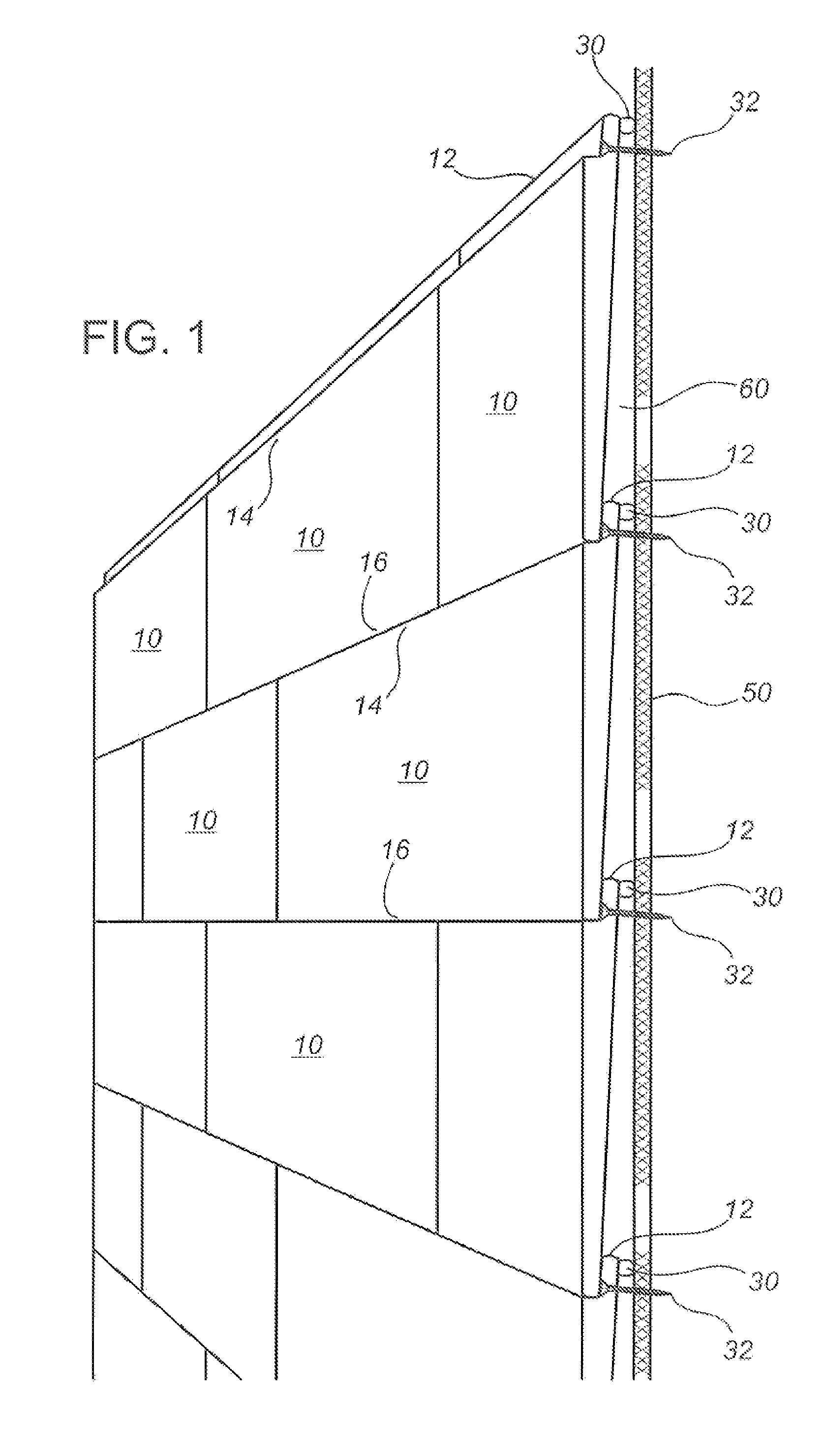
[0048]FIG. 1 illustrates a mounted assembly of cladding panels 10 in accordance with a preferred embodiment of the invention, and FIG. 2 illustrates a typical horizontal joint between mounted panels 10. The panels 10 are shown as being rectangular in shape, but other shapes are also possible without departing from the concept of the invention. Each panel 10 has a front face 20 and rear face 22. In the embodiment shown in FIGS. 1 and 2, the thickness of panel 10 tapers from a top thickness WT at upper edge 14 of panel 10 to a bottom thickness WL (which is less than top thickness WT) at lower edge 16 of panel 10. Panel 10 is formed with a horizontal notch so as to form a continuous upstand 12 along upper edge 14. Upstand 12 is inset from front face 20 such that a continuous ledge 15 is formed between upstand 12 and upper edge 14. Ledge 15 is preferably formed such that when panel 10 is mounted to a support structure 50, with front face 20 in a substantially vertical orientation, ledge...


PUM


Abstract

In a precast cladding panel system requiring no cast-in mounting hardware, each panel has a continuous notch along its upper edge, forming a ledge adjacent the panel's front face, and an upstand adjacent the panel's rear face. Each panel is mounted to a supporting structure using fasteners installed through openings formed in the upstand. The panels are configured such that their lower edges fit into the notches of underlying panels, with the front faces of all panels being substantially co-planar, aided by spacer means fastened to the supporting structure adjacent to the lowermost panel course. Air circulation behind the installed panel assembly is facilitated by spaced bumpers fastened to the supporting structure so as to space the panel upstands away therefrom. Alternatively, the panels may be mounted with the upstands directly against the supporting structure, with the panels having vertical air channels formed into the upstands and rear panels faces as appropriate.

Description

CROSS-REFERENCE TO RELATED APPLICATIONS[0001]This application claims the benefit, pursuant to 35 U.S.C. 119(e), of U.S. Provisional Application No. 60 / 771,854, filed on Feb. 10, 2006, and said provisional application is incorporated herein by reference in its entirety.FIELD OF THE INVENTION[0002]The present invention relates in general to precast cladding panels, and in particular to precast cladding panels that do not require hangers or other mounting hardware to be cast into the panels.BACKGROUND OF THE INVENTION[0003]Precast panels of various sizes and shapes are widely used as cladding on building walls, serving as components of building envelope systems intended to prevent infiltration of rain and outside air into the building. Precast cladding panels are commonly made of concrete, but may also be made with other cast materials known in the construction field. Concrete cladding panels are common on large structures such as office buildings, but they are also used on residential...

Claims


Application Information

Patent Timeline
Patent Type & Authority Patents(United States)
IPC IPC(8): E04B1/70
CPCE04F13/14E04F13/007E04F13/0871E04F17/00E04F19/061
Inventor KUELKER, PETER
Owner KUELKER PETER
Why Eureka
Try Eureka