Electrical connector

a technology of electrical connectors and connectors, applied in the direction of coupling device connections, coupling parts engagement/disengagement, incorrect coupling prevention, etc., can solve the problems of significant cost disadvantage and comparatively high manufacturing cost of known plug connections, and achieves improved handling, reduced vibration in use, and manufactured inexpensively

Active Publication Date: 2010-04-13
WOODHEAD IND INC
View PDF7 Cites 31 Cited by
  • Summary
  • Abstract
  • Description
  • Claims
  • Application Information

AI Technical Summary

Benefits of technology

[0007]The present invention is concerned with the problem of providing an improved embodiment for a plug connection of the type specified initially which in particular makes it possible to achieve improved handling, reduced vibration in use, and can be manufactured inexpensively.

Problems solved by technology

However, the known plug connection is comparatively expensive to manufacture since an additional component, namely the additional compression springs, must be incorporated in an additional production step.
However, since series-produced parts are involved in the manufacture of the present invention, a significant cost disadvantage is thereby obtained.

Method used


Image

  • Electrical connector
  • Electrical connector
  • Electrical connector

Examples


Embodiment Construction

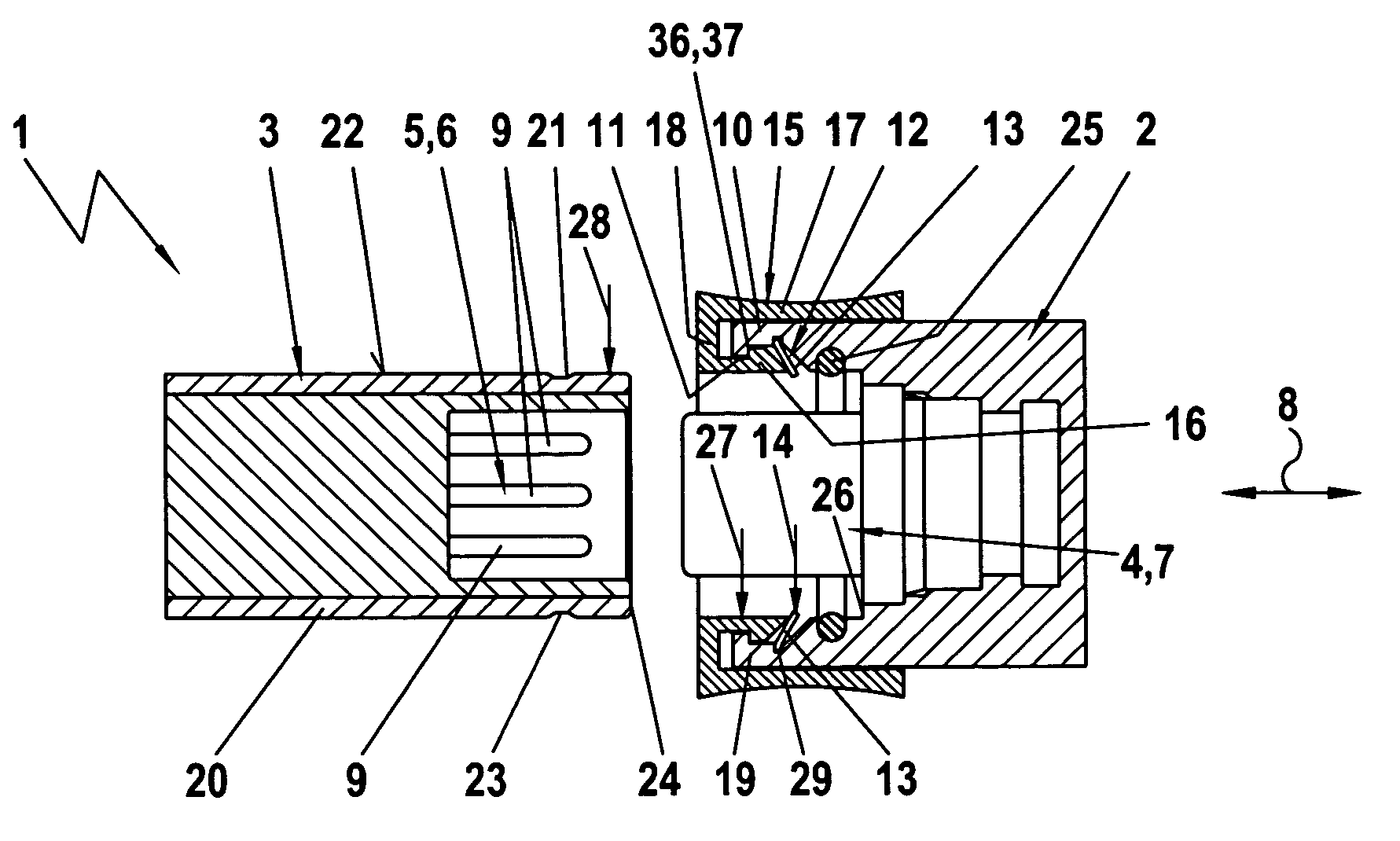
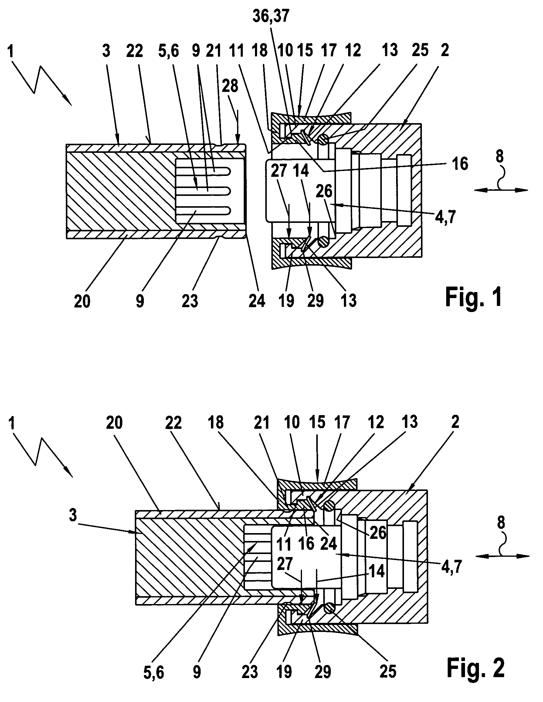
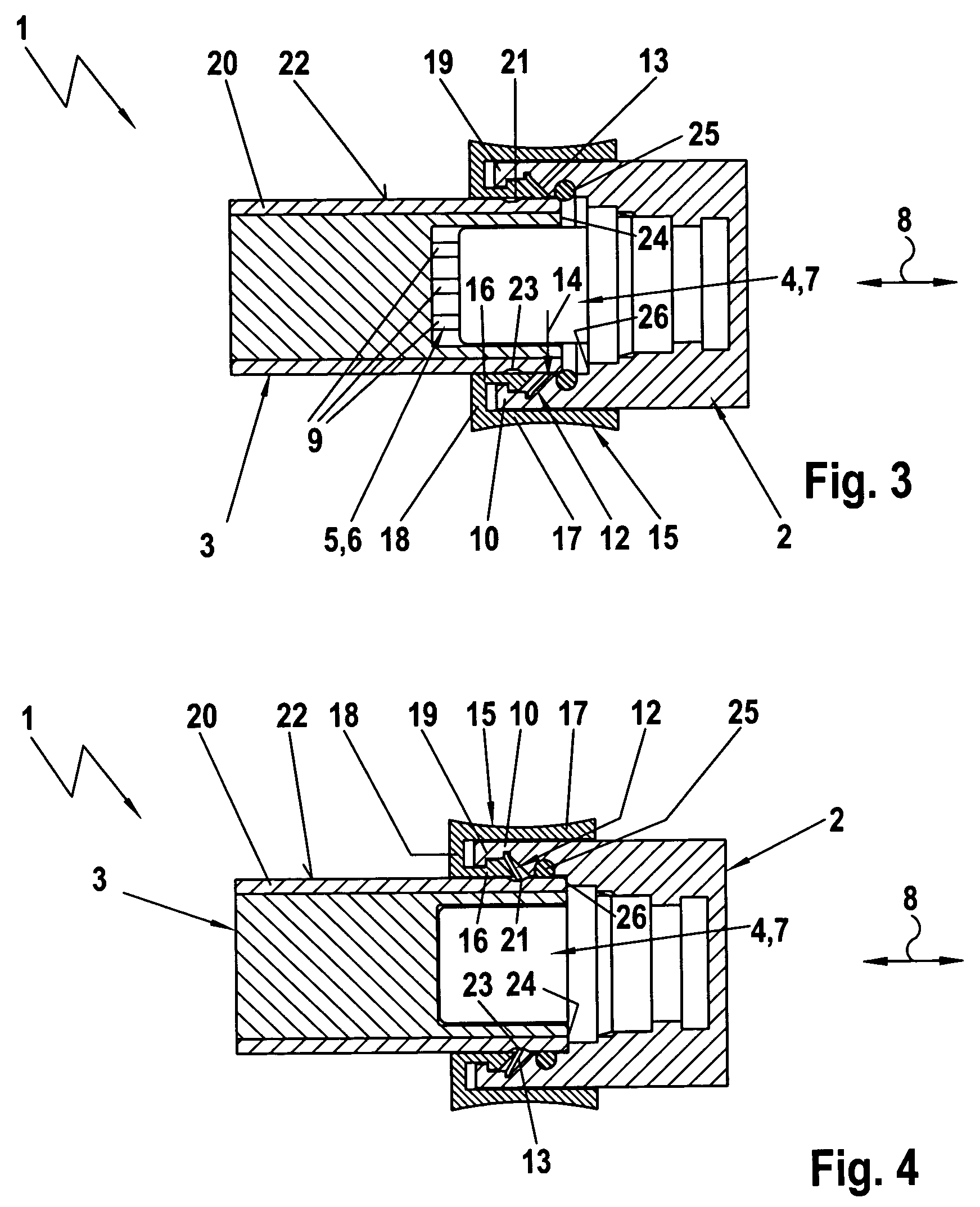
[0025]In accordance with FIGS. 1 to 6, an electrical plug connector 1 according to the invention comprises a pair of mating electrical connectors including first plug section 2 and a second plug section 3. The plug connector 1 is used for the electrical connection of at least two electrical conductors or wires included in cords or cables such as shown at 35 in FIGS. 5 and 10. The first plug section 2 contains in its interior a first electrical coupling section 4. Similarly, the second plug section 3 contains a second electrical coupling section 5 in its interior. In the embodiment of FIGS. 1 to 6, the second coupling section 5 is constructed as a plug 6 (i.e., having male connecting elements in the form of pins 9, whilst the first coupling section 4 is formed by a socket 7 with female connecting elements such as sleeves. The two coupling sections 4, 5 are constructed complementary to one another so that plug 6 and socket 7 can be inserted one into the other in a plug or connect / disc...


PUM


Abstract

An electrical plug connector including two mating connectors. A first plug section includes a receiving sleeve which encircles the first coupling section and which carries a locking element which includes flexible tabs movable between a locking position and an unlocking position and which are pre-stressed in its locking position. Held displaceably on the receiving sleeve is a sliding or release sleeve which may be manually moved axially to engage the locking element and release the mating connector. The second plug section has a plug tube which surrounds the second coupling section. When the plug tube is inserted in the receiving sleeve, the locking element rests on the outside of the plug tube in its locking position whereby the plug sections are connected. The connectors can be released by actuating the sliding sleeve to move the locking element into its unlocking position.

Description

RELATED APPLICATION[0001]This application claims benefit of an application filed under the Patent Cooperation Treaty entitled “Electrical Plug-In Connection”, Application No. PCT / DE2004 / 000793, filed Apr. 14, 2004, Publication No. WO 2004 / 109865 A1, Publication Date of Dec. 16, 2004, which is entitled to the priority date of German Utility Model entitled “Elektrische Steckverbindung”, Application No. 103 24 794.7, filed May 31, 2003.FIELD OF THE INVENTION[0002]The present invention relates to an electrical connector including mating male and female connectors, sometimes referred to as “quick disconnect” connectors.BACKGROUND OF THE INVENTION[0003]A plug connector is disclosed, for example, in German Patent DE 197 49 130 C1 and has two complementary, mating plug sections which contain mutually complementary electrical coupling sections. The first plug section comprises a receiving sleeve which encircles the first coupling section and which has on its inside a locking element in the f...

Claims


Application Information

Patent Timeline
Patent Type & Authority Patents(United States)
IPC IPC(8): H01R13/627
CPCH01R13/6277H01R13/627H01R13/629
Inventor EISSNER, ROLANDROLLER, NORBERT
Owner WOODHEAD IND INC
Why Eureka
Try Eureka