
Array ultrasonic transducer having piezoelectric devices

a piezoelectric device and ultrasonic transducer technology, applied in the field of ultrasonic transducers, can solve the problems of increasing the number of transducer elements, increasing the difficulty of connecting lead wires to the elements, and narrowing the width of each transducer element, so as to achieve excellent machinability, high reliability, and high efficiency in the coefficient of electromechanical coupling

Active Publication Date: 2010-04-13
OLYMPUS CORP
View PDF14 Cites 11 Cited by
  • Summary
  • Abstract
  • Description
  • Claims
  • Application Information

AI Technical Summary

Benefits of technology

The present invention provides a method of manufacturing an ultrasonic transducer that allows for easy lead wire connections and reduces the risk of breakage and decreased reliability. The method involves dividing the transducer elements into smaller elements and coating them with a conductive sheet to prevent lateral vibrations from affecting the longitudinal vibrations. The method also includes steps for forming first and second division steps, as well as a masking step. The use of a thin conductive sheet and the absence of wiring to elements consisting of two or more sub elements are also features of the invention. Overall, the invention provides a more reliable and efficient ultrasonic transducer that is easier to manufacture and has improved performance.

Problems solved by technology

However, the conventional device has a problem in which, when a transducer element is divided into smaller elements such that the transducer elements do not have a proper resonant frequency in the lateral direction in order to prevent lateral vibrations that are superposed on longitudinal vibrations from affecting the longitudinal vibrations, the number of transducer elements inevitably increases and the width of each transducer element becomes narrower, such that the difficulty in connecting lead wires to the elements increases.
Also, there has been a problem in which, when an FPC board is directly connected to transducer sub elements each having a small width, the stiffness of the FPC board remains as a residual stress such that the reliabilities of the ultrasonic transducers are reduced.

Method used


Image

  • Array ultrasonic transducer having piezoelectric devices
  • Array ultrasonic transducer having piezoelectric devices
  • Array ultrasonic transducer having piezoelectric devices

Examples


first embodiment

[0144]First, the first embodiment to which the present invention is applied is explained by referring to FIGS. 6 through 15.

[0145]FIG. 6 is a flowchart showing a method of manufacturing an ultrasonic transducer according to the first embodiment. FIG. 7 is a perspective view of the acoustic matching layer / piezoelectric device mounting step. FIG. 8 is a perspective view of the first division step. FIG. 9 is a top view of the first division step. FIG. 10 is a perspective view of the piezoelectric device / board mounting step. FIG. 11 is a top view of the piezoelectric device / board mounting step. FIG. 12 is a perspective view of the masking step. FIG. 13 is a top view of the conductive sheet coating step in the first embodiment. FIG. 14 is a top view of the second division step in the first embodiment. FIG. 15 is a top view of the step after a masking member is removed.

[0146]First, in the acoustic matching layer / piezoelectric device mounting step executed in step S11 shown in FIG. 6, an a...

second embodiment

[0155]The flowchart shown in FIG. 16 is different from that shown in FIG. 6 in that the flowchart shown in FIG. 16 does not include the masking step executed in step 14 or the masking member removal step executed in step s17, both of which are shown in FIG. 6. In other words, the method of manufacturing an ultrasonic transducer is characterized by not requiring the masking step.

[0156]Specifically, in the conductive sheet coating step executed in step S15 that is executed subsequently to the piezoelectric device / board mounting step executed in step s13, portions that are close to the mounting portions between the piezoelectric devices 1032 and the circuit board 1051 that were connected to each other in the piezoelectric device / board mounting step executed in step s13 are coated with the conductive sheet 1071 in such a manner that the conductive sheet 1071 covers the portions on both piezoelectric device 1032 and circuit board 1051. The conductive sheet 1071 can be made of a conducti...

third embodiment

[0171]Next, the present invention will be explained.

[0172]FIG. 21 shows an outline of an ultrasound endoscope according to the third embodiment of the present invention.

[0173]An ultrasound endoscope 2001 comprises an operation unit 2006 at the proximal end of an insertion unit 2002. A universal cord 2007 extends from a side portion of the operation unit 2006. The universal cord 2007 comprises, at one end thereof, a scope connector 2008 that is to be connected to a light source (not shown). Further, the scope connector 2008 is connected to an ultrasonic observation device (not shown) via a cable.

[0174]The insertion unit 2002 comprises a distal end 2003, a bending unit 2004 that can arbitrarily curve, and a flexible tube 2005, in this order from the distal end side and in the connected state. The operation unit 2006 comprises an angulation control knob 2006a, and by operating this angulation control knob 2006a, the bending unit 2004 can be curved.

[0175]FIG. 22 is an enlarged view show...


PUM

PropertyMeasurementUnit
radiusaaaaaaaaaa
widthaaaaaaaaaa
diameteraaaaaaaaaa

Abstract

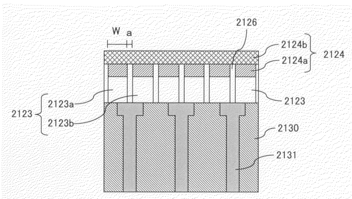
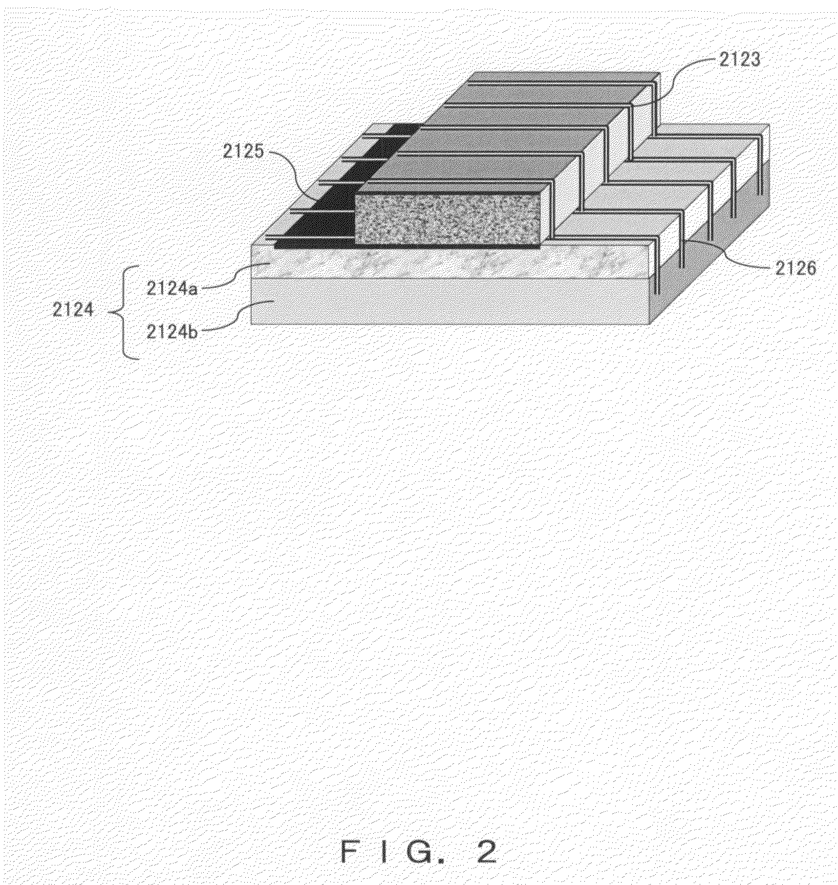
An ultrasonic transducer in which lead wire connection is facilitated even when piezoelectric devices are divided in order to prevent lateral vibrations from affecting longitudinal vibrations is manufactured by a method comprising: a step in which first dicing grooves are formed on an acoustic matching layer and a piezoelectric device plate that are mounted together in order to form a plurality of piezoelectric devices; a step in which a board and the respective piezoelectric devices are connected together; a step in which surfaces in the vicinity of locations at which the board and the piezoelectric devices are connected together are coated with a conductive sheet; and a step in which the plurality of transducer elements are formed by forming second dicing grooves between the first dicing grooves formed on the piezoelectric devices and the board that is coated with the conductive sheet and on the acoustic matching layer.

Description

TECHNICAL FIELD[0001]The present invention relates to an ultrasonic transducer, to be used in an endoscope, for obtaining ultrasonic cross-sectional images by transmitting and receiving ultrasound to and from body cavities and to a method of manufacturing such an ultrasonic transducer, and particularly to an ultrasonic transducer that does not cause crosstalk or disturbances in ultrasonic beams, and to a method of manufacturing such an ultrasonic transducer.BACKGROUND ART[0002]Conventionally, a diagnostic ultrasound system formed for clinics. This system comprises an ultrasonic transducer, a signal transmitting unit, a signal receiving unit and a display unit. The signal transmitting unit is generated the pulse signals and connected with the ultrasonic transducer to have the pulse signals transmitted into the ultrasound by above transducer. The signal receiving unit is connected with ultrasonic transducer for receiving echo signals varied with the ultrasonic pulse echo from the tiss...

Claims


Application Information

Patent Timeline
Patent Type & Authority Patents(United States)
IPC IPC(8): H01L41/08H10N30/00
CPCB06B1/0622Y10T29/42Y10T29/49005
Inventor SAWADA, YUKIHIKOMIZUNUMA, AKIKOWAKABAYASHI, KATSUHIROIMAHASHI, TAKUYASATO, SUNAO
Owner OLYMPUS CORP
Learn More