Digital loop filter for all-digital phase-locked loop design

a phase-locked loop and filter technology, applied in the field can solve the problems of the design of digital loop filters, the inability to reduce the jitter effect of output signals, and so as to reduce the period jitter of output signals of pll, reduce the output jitter of all-digital pll designs, and reduce the jitter effect of input signals

Active Publication Date: 2010-04-13
NAT CHIAO TUNG UNIV
View PDF4 Cites 2 Cited by
  • Summary
  • Abstract
  • Description
  • Claims
  • Application Information

AI Technical Summary

Benefits of technology

[0009]In view of the foregoing shortcomings of the prior art that cannot reduce the period jitter of the output signal of the PLL effectively, the inventor of the present invention developed a digital loop filter for lowering the output jitter of the all-digital PLL design.
[0010]Therefore, it is a primary objective of the present invention to provide a digital loop filter for an all-digital PLL design, and the digital loop filter is installed in an all-digital PLL for reducing the jitter effect of an input signal to the all-digital PLL as well as the jitter effect of an output signal effectively, such that the all-digital PLL can maintain tracking and locking the input signal frequency and the phase.
[0011]Another objective of the present invention is to provide a digital loop filter for an all-digital PLL design, and the digital loop filter adopts an all-digital PLL related design technology to improve the electric leakage issue of a traditional analog PLL and provides a feasible solution to the difficulty of being operated at a low voltage, so as to enhance the cost structure and product competitiveness substantially.

Problems solved by technology

As a result, the output of the accumulator will become unstable, and the period jitter of the output signal of the PLL cannot be reduced, and thus causing problems to the design of digital loop filters.
However, if the jitter of the input signal is very large, the method of updating an anchor register cannot suppress the jitter effect of the input signal on the PLL effectively, and thus the method cannot reduce the jitter effect of the output signal to the PLL, and the issue of period jitters still exists.

Method used


Image

  • Digital loop filter for all-digital phase-locked loop design
  • Digital loop filter for all-digital phase-locked loop design
  • Digital loop filter for all-digital phase-locked loop design

Examples


Embodiment Construction

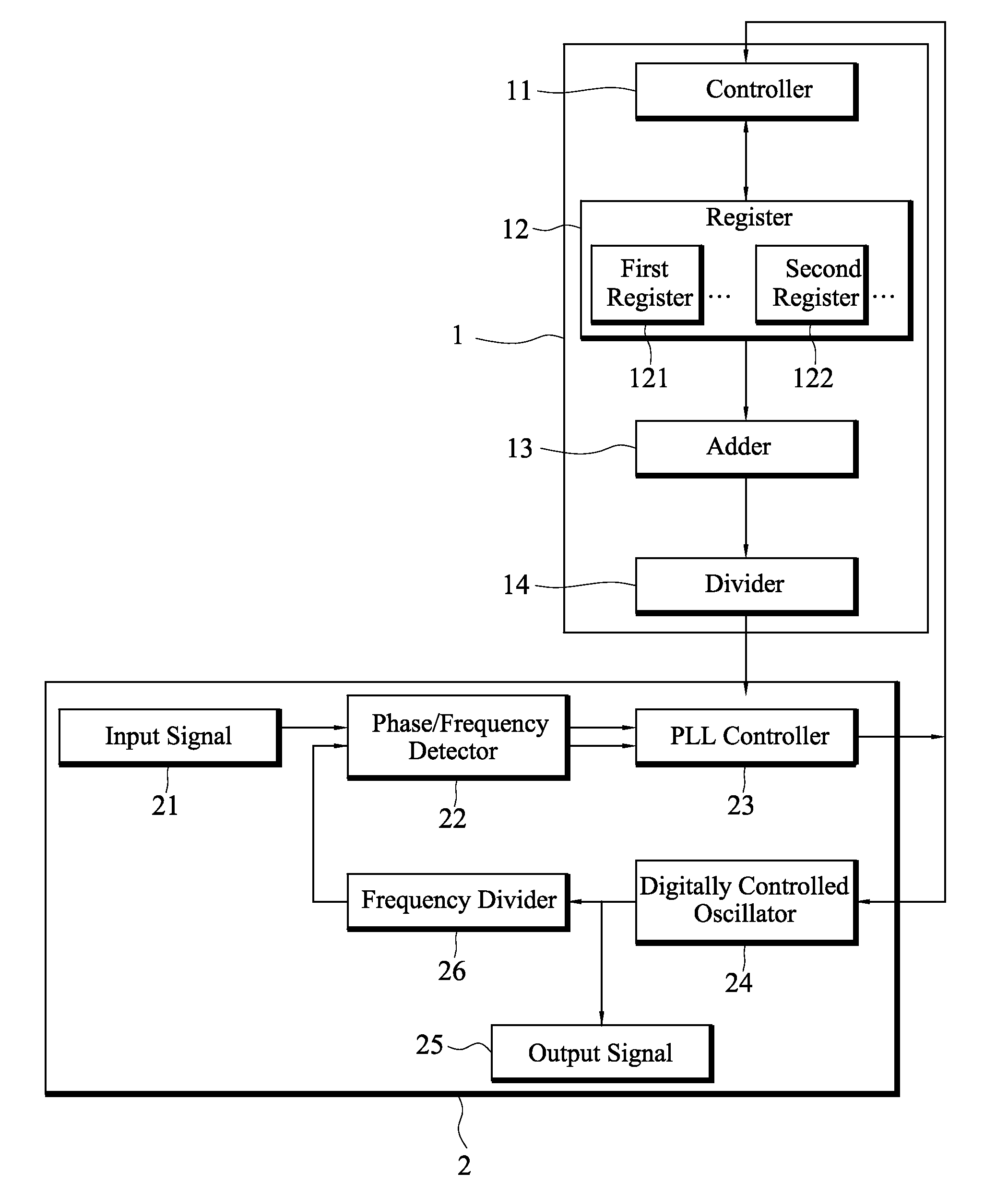
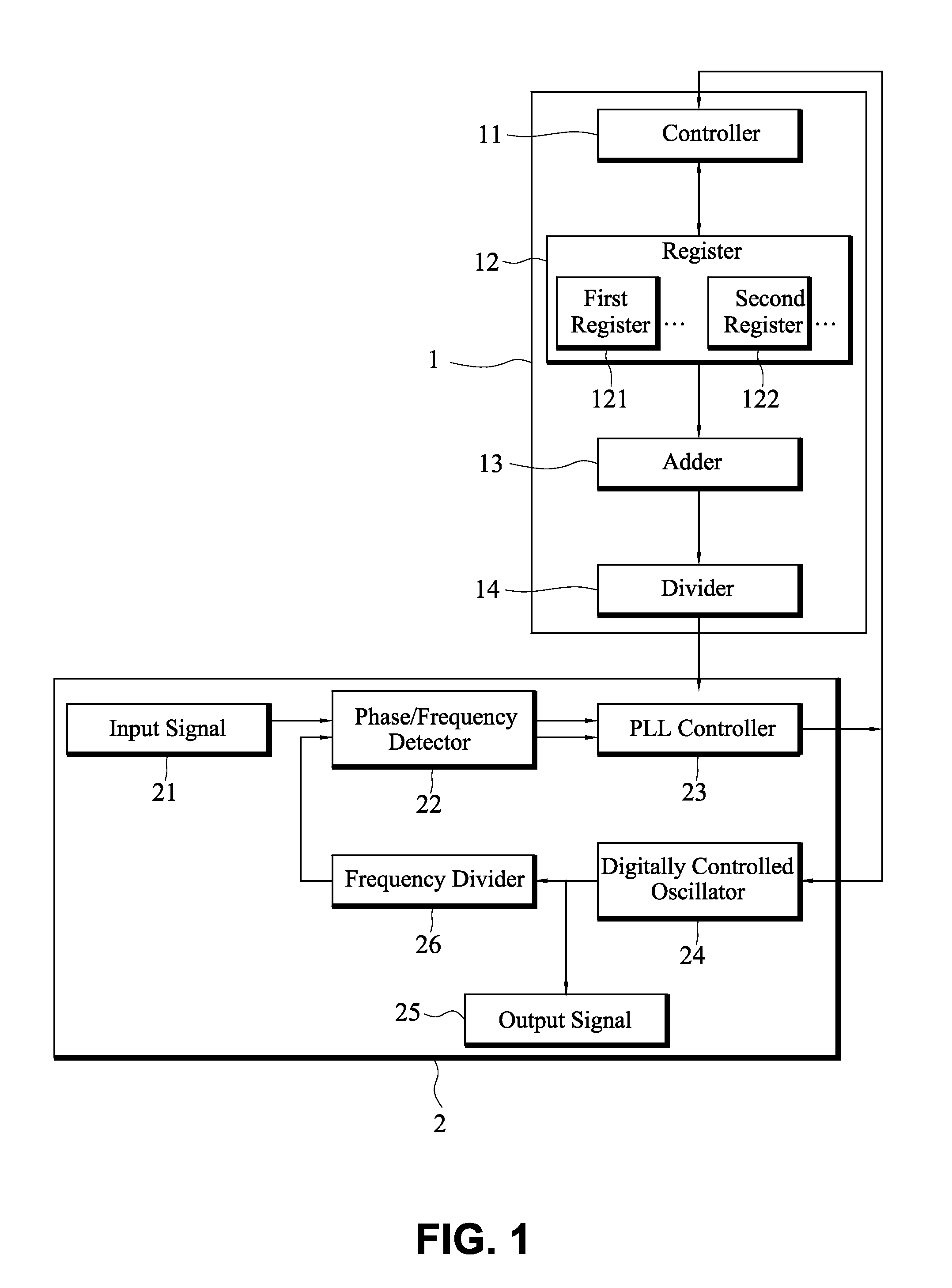
[0015]The present invention relates to a digital loop filter for an all-digital PLL design. With reference to FIG. 1 for a schematic view of a structure of a digital loop filter 1 installed in an all-digital PLL 2, the digital loop filter 1 includes a controller 11 for receiving a DCO control code and another DCO control code transmitted from a phase-locked loop (PLL) controller in the all-digital PLL 2, and updating the DCO control code and the other DCO control code into a plurality of registers 12.

[0016]The plurality of registers 12 are provided for storing the DCO control code and the other DCO control code updated and transmitted by the controller 11, wherein the plurality of registers 12 include a plurality of first registers 121 (such as M=T0˜T(M−1)) and a plurality of second registers 122 (such as K=TM˜T(M+K−1)), and the plurality of first registers 121 are provided for storing the DCO control code transmitted from the controller 11, and the plurality of second registers 122...


PUM


Abstract

A digital loop filter installed in an all-digital phase-locked loop (PLL) receives a digitally controlled oscillator (DCO) control code transmitted from a PLL controller in the all-digital PLL, and calculate an average value, such that the PLL controller can produce another DCO control code by the average value for controlling and adjusting an output signal of a digitally controlled oscillator (DCO) in the neighborhood of the average value to maintain compensating a phase / frequency difference with an input signal, so as to minimize the jitter effect of the input signal on the all-digital PLL, reduce the jitter effect of the output signal, and keep tracking and locking the frequency and the phase of the input signal.

Description

BACKGROUND OF THE INVENTION[0001]1. Field of Invention[0002]The present invention relates to a digital loop filter installed in an all-digital phase-locked loop (PLL) for reducing the jitter effect of an input signal to the all-digital PLL as well as reducing the jitter effect of the output signal, such that the all-digital PLL can keep tracking and locking the frequency and phase of the input signal.[0003]2. Description of Related Art[0004]As the consumption and importance of communication products increase and integrated circuits develop rapidly, the demand for communication integrated circuits increases correspondingly, wherein a phase-locked loop (PLL) is one of the common circuits applied for the modulation and demodulation in the communication field and used as a frequency synthesizer on a radio system or a clock signal recovery system with digital circuits.[0005]The principle of the PLL is to track and lock the phase and the frequency of the input signal and the output signal...

Claims


Application Information

Patent Timeline
Patent Type & Authority Patents(United States)
IPC IPC(8): H03L7/06H03L7/08H03L7/085
CPCH03L7/093H03L2207/50
Inventor LEE, CHEN-YICHUNG, CHING-CHE
Owner NAT CHIAO TUNG UNIV
Why Eureka
Try Eureka