
Pointing device for use in air with improved cursor control and battery life

Active Publication Date: 2010-04-13
LOGITECH EURO SA
View PDF25 Cites 101 Cited by
  • Summary
  • Abstract
  • Description
  • Claims
  • Application Information

AI Technical Summary

Benefits of technology

[0018]The present invention is an apparatus and method for improved cursor control in a device which can operate both on a work surface and in air. Cursor resolution is reduced as the user engages with the device for clicking, leading to more precise movement closer to the target, as well as reduced parasitic and other unintentional motion of the cursor during clicking. Moreover, one aspect of the present invention is an apparatus and method for improved battery life in an in-air pointing device. In another aspect, the present invention is a method a system for improved user interface interaction, for UI controls such as sliders, pop-up boxes, menus, lists and button groups.
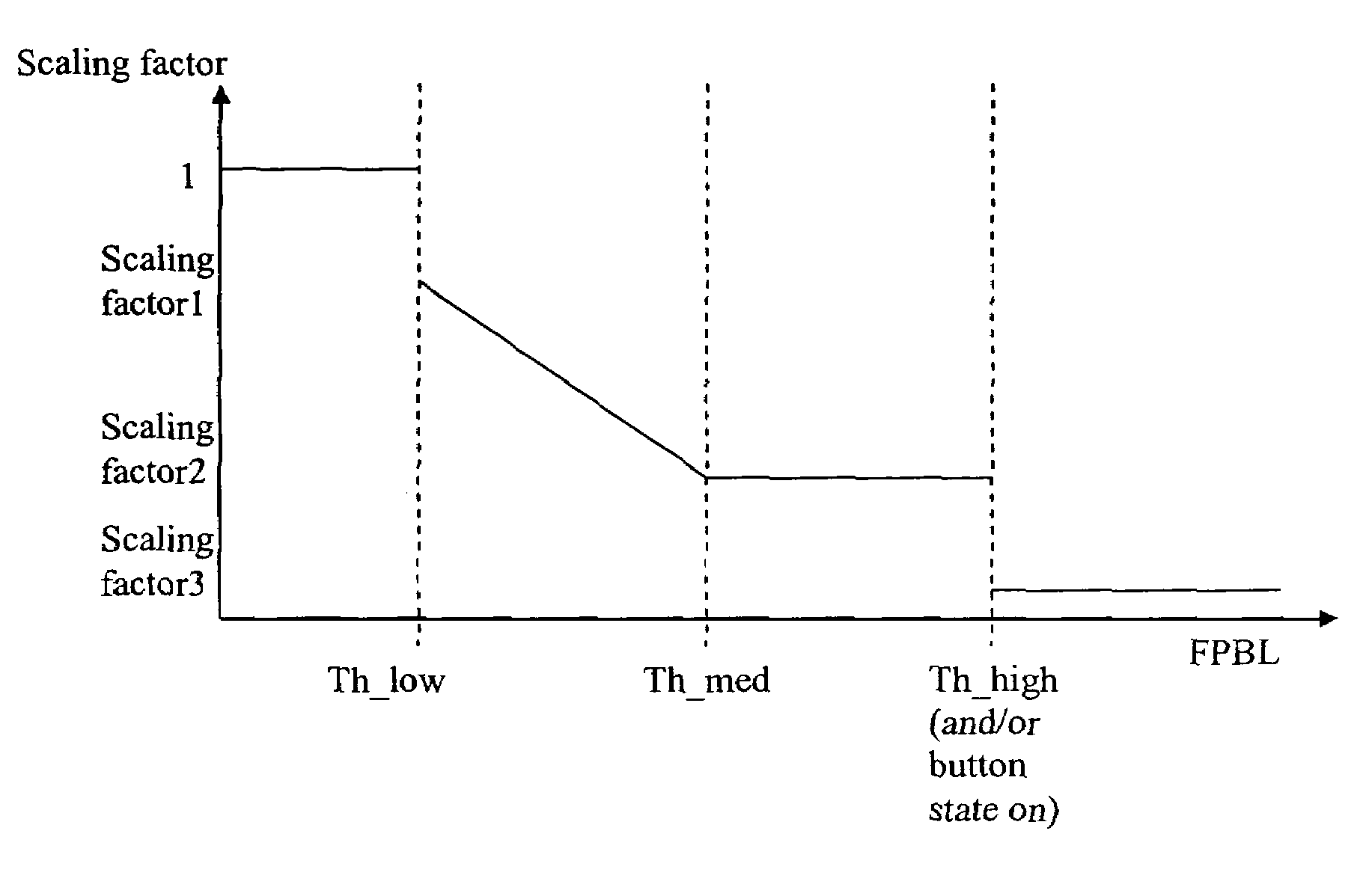
[0019]A device in accordance with an embodiment of this invention improves cursor control by allowing the user to momentarily reduce the resolution when more precision is needed. Large resolution is needed to reach the desired zone on the screen (e.g., to make sure that the entire screen can be reached with a comfortable wrist movement). When the target zone is reached, the user can change the system behavior and make it more precise by reducing the resolution in a progressive way. This is done until the (small) target is reached. Eventually, the resolution gets back to its nominal (high) value.
[0020]In one embodiment, the change in resolution is based upon the presence of a user's finger on a smart button, and / or on the pressure exerted by the user's finger on the smart button. The smart button includes, in one embodiment, a touchpad which detects the presence of a user's finger as well as the pressure exerted by that finger. The system measures the touchpad pressure. When the pressure is above a predefined value, the resolution is decreased in direct proportion to the applied pressure (pressure*resolution=constant). In one embodiment, eventually, when a very large pressure is detected (e.g., above a predefined threshold), the cursor is frozen, allowing for a skating equivalent (e.g., the hand can be moved to a more relaxed position without moving the cursor), when the position is reached, pressure is lowered and the cursor moves again from where it was before the hand was repositioned. In another embodiment, when a very large pressure is detected, the cursor resolution is minimized, but is not frozen, thus allowing for operations such as drag and drop. Such embodiments reduce or eliminate parasitic cursor motion at click instant. It should be noted that these enhancements can be applied equally well to an “on-desk” mouse.
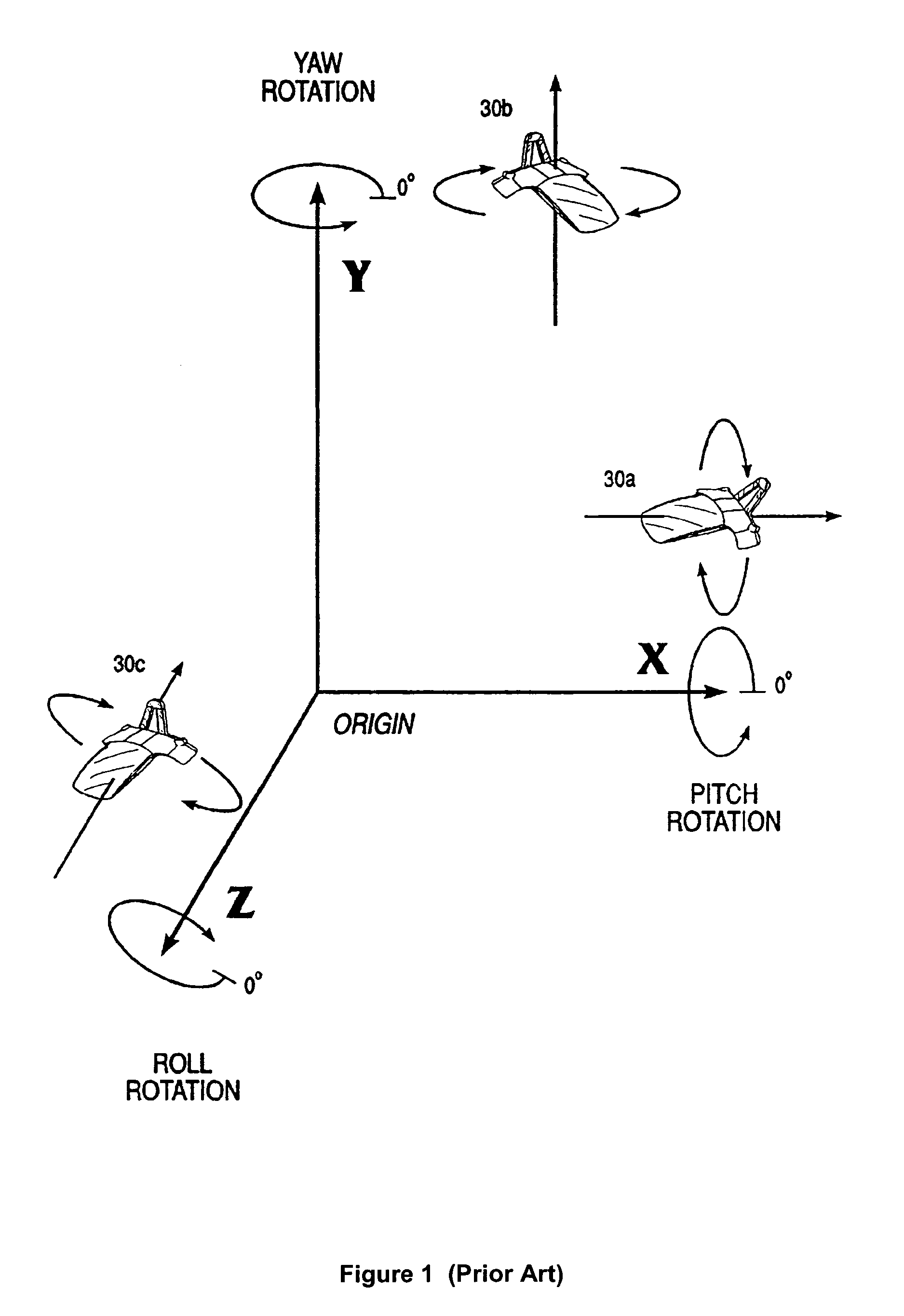
[0021]In one embodiment, a User Interface (UI) slider is controlled more easily by applying pulse feedback. In the slider control mode, when either the yaw or pitch angle has changed by a predefined quantity (angular increment), a feedback pulse is applied to alert the user that the corresponding slider position has been incremented and a notification is sent to the host, thus alleviating the need to carefully watch for the screen while controlling the slider position. The choice of whether yaw (x-axis) or pitch angle (y-axis) increments are used depends on the slider orientation. In one embodiment, this is defined by the application: a horizontal slider feedback pulse is controller by a yaw angular increment and the vertical slider feedback pulse is controlled by a pitch angular increment. As in Microsoft Windows from Microsoft Corp. (Redmond, Wash.), in one embodiment, the active UI control is the control on which the cursor is located, dedicated buttons allow to directly select the application containing that control without having to look at the cursor to position it on the desired application. An air-control type of button is linked, in one embodiment, to a dedicated UI. For instance, pressing a button dedicated to volume will, in one embodiment, bring up the volume control on a display as well as increasing the sound volume. In this example, moving the device down decreases the volume, and moving it up increases the volume, while providing the user with a autonomous feedback separate from the visual feedback on the screen. The above can be applied equally well to other UI controls such as to list box, pop-up menu, or button group.
[0022]In one embodiment of the present invention, extended battery life is obtained by relying on an inclinometer that monitors the system inclination at a specified polling rate. Let us assume the device is initially in idle state. When the system detects meaningful orientation change (for example larger than 10°) the system is categorized as active for certain duration (for example 10 sec). If no meaningful orientation change is detected during a defined time window, the system is categorized as idle. When in idle, the same inclination monitoring happens except it happens at a lower polling rate. Some power hungry blocks, for example those that determine cursor movement, a LED block indicating of air tracking, or a RF transmitter block, are also disabled while in idle. By reducing the polling rate when in idle and disabling some blocks, battery consumption is largely reduced. When a meaningful inclination change is detected, the system goes back in an active state where the nominal polling rate is applied and all blocks are activated, including the LED block that indicates the system is ready to track.

Problems solved by technology

Apart from being in a more relaxed position, the user is often not close enough to a desk to rest a mouse on it.
At least for the reasons discussed above, such input devices which can only function when placed on a work surface (e.g., a desk or a mouse pad) are not optimal for use in such environments.
However, known pointing devices that work “in-air” present several challenges.
For instance, clicking at a specific desired location (e.g., on an icon on a display associated with the computer) is difficult when maneuvering the pointing device in air.
Moreover, a device which operates in air may be subject to significant ongoing battery consumption in certain scenarios, such as if the user were to continually hold the device in his hand while watching a movie.
Furthermore, easy and intuitive user interfaces are not available in in-air input devices for computers, such as for controlling volume and so on.
Clicking at a precise location with an in-air device is problematic.
To begin with, controlling the movement of the cursor accurately is difficult because holding the device in the air makes complete control of orientations difficult.
Typically, such parasitic motion results in a missed click (the operating system suppresses click when the cursor is not steady over its target or when the cursor is no longer on the icon at button release).
Moreover, there is an inherent trade-off in free-space devices—given the limited angle span of a human wrist, a large resolution is needed in order for the user to easily reach the entire screen with a single wrist movement; however having too large a resolution would result in random cursor movements attributable to normal tremor of human hands and parasitic clicking motion.
However, such solutions are cumbersome to the user, since they require continual added actions (pressing and releasing the trigger button) from the user.
Such pre-existing solutions result in a cumbersome, complicated and non-intuitive interaction of the user with the user interface.
Existing devices also suffer from the reduced battery life that results from moving the device unintentionally over an extended period of time, for example by holding the device while watching a movie or listening to music.
However, such a trigger button makes the system less intuitive to use.
However, none of these patents or publications provides an air-scroller type of mechanism.
Further, none of these patents or publications provides the user with feedback regarding the desired action being taken, without the user attentively looking to the screen until the desired position is reached.
Given the device is also used for media application, where the user is in a lean-back posture, precise positioning using visual feedback is cumbersome.

Method used


Image

  • Pointing device for use in air with improved cursor control and battery life
  • Pointing device for use in air with improved cursor control and battery life
  • Pointing device for use in air with improved cursor control and battery life

Examples


Embodiment Construction

[0040]The figures (or drawings) depict a preferred embodiment of the present invention for purposes of illustration only. It is noted that similar or like reference numbers in the figures may indicate similar or like functionality. One of skill in the art will readily recognize from the following discussion that alternative embodiments of the structures and methods disclosed herein may be employed without departing from the principles of the invention(s) herein.

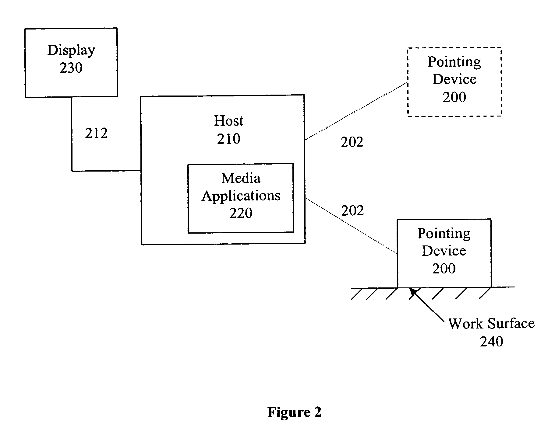
[0041]FIG. 2 is a block diagram of a pointing device 200 used with a host system 210 with media applications 220, an associated display 230.

[0042]The pointing device 200 is a device in accordance with an embodiment of the present invention. It functions as a conventional pointing device (e.g., mouse) when placed on a work surface 240. In addition, it functions as an in-air pointing device when the user lifts it away from work surface 240. This transition from work surface mode to in-air mode is completely seamless for the use...


PUM


Abstract

One aspect of the present invention is an apparatus and method for improved cursor control in a device which can operate both on a work surface and in air. Cursor resolution is reduced as the user engages with the device for clicking, leading to more precise movement closer to the target, as well as reduced parasitic and other unintentional motion of the cursor during clicking. Moreover, one aspect of the present invention is an apparatus and method for improved battery life in an in-air pointing device. In another aspect, the present invention is a method a system for improved user interface interaction, for UI controls such as sliders, pop-up boxes, menus, lists and button groups.

Description

CROSS-REFERENCES TO RELATED APPLICATIONS[0001]This application is related to co-pending application Ser. No. 11 / 356,386 entitled “Dead Front Mouse” which was filed on Feb. 16, 2006, which is hereby incorporated herein in its entirety.BACKGROUND OF THE INVENTION[0002]1. Field of the Invention[0003]The invention relates generally to input devices, and more particularly, to improving handling and battery life of a mouse which can also be used in-air.[0004]2. Description of the Related Art[0005]The personal computer (PC) is increasingly becoming a media center, which users use to store and play music, videos, pictures, etc. As a result, the PC is also increasingly seen in the living room. Users are often in more relaxed positions (e.g., lounging on a couch) when in the living room, or more generally, when interacting with media (such as when watching a video), than when using the PC for more traditional interactions. Apart from being in a more relaxed position, the user is often not clo...

Claims


Application Information

Patent Timeline
IPC IPC(8): G06F3/033G09G5/08
CPCG06F3/0346G06F3/04847G06F3/0482G06F2203/04805
Inventor PIOT, JULIENEGLOFF, OLIVIERARRIGO, SIMONEGATTONI, LUCASRAMOND, NICOLASVANRELL, DAVID TARONGI
Owner LOGITECH EURO SA
Learn More