Gear

a technology of gears and gearing elements, applied in the direction of gearing elements, belts/chains/gears, hoisting equipments, etc., can solve the problems of uneven deformation of thin-walled sections, high torque fluctuations, and high risk of cracks, so as to achieve easy deformation, control torque fluctuations, and eliminate backlash

Inactive Publication Date: 2010-04-20
ENPLAS CORP
View PDF19 Cites 14 Cited by
  • Summary
  • Abstract
  • Description
  • Claims
  • Application Information

AI Technical Summary

Benefits of technology

[0015]In the invention according to claim 1, when the gear meshes with the partner gear, a gap equivalent to backlash is formed between the two gears. However, because the overhanging section within the thin-walled section can fill the gap, the backlash can be eliminated. The tooth crest corresponding section is formed thinner than the thickness of the overhanging section. Therefore, when the gear is meshed with the partner gear, the tooth crest corresponding section can be easily deformed in accompaniment to the deformation of the overhanging section. Therefore, the torque fluctuations can be controlled. The formation of cracks and the like attributed to stress concentration can be prevented, and the decrease in positioning accuracy due to overshoot can be prevented.
[0016]In the invention according to claim 2, the overhanging section, the tooth crest corresponding section, and the tooth flank corresponding section are sequentially and consecutively formed. Regarding thickness, the tooth crest corresponding section positioned between the overhanging section and the tooth flank section is the thinnest, followed by the overhanging section. The tooth flank corresponding section is the thickest. This order is also the order in which deformation is easily performed. In other words, when the overhanging section becomes deformed during meshing, the tooth flank corresponding section becomes a reactive force with little deformation. The most easily deformed tooth crest corresponding section becomes deformed between the overhanging section and the tooth flank corresponding section.
[0017]In the invention according to claim 3, the connecting section between the overhanging section and the bottom land corresponding section is easily deformed. Therefore, the deformation of the overhanging section is further facilitated. In other words, the overhanging section is sandwiched between the tooth crest corresponding section and the connecting section that are both easily deformed. As a result, deformation is further facilitated.
[0018]In the invention according to claim 4, the intermediate section at the tip of the overhanging section is formed having almost the same shape as a portion of the tooth flank. The projection amount in the intermediate section is set to be the greatest. Therefore, when the overhanging section is deformed, the intermediate section becomes flush with the tooth flank and does not interfere with smooth meshing between gears.

Problems solved by technology

Therefore, the deformation of the thin-walled section is not necessarily performed smoothly, and torque fluctuations are likely to occur.
Because stress is concentrated near the top, cracks are likely to form as a result of use over a long time.
Furthermore, overshooting occurs, and positioning accuracy decreases.

Method used


Image

  • Gear
  • Gear
  • Gear

Examples


first embodiment

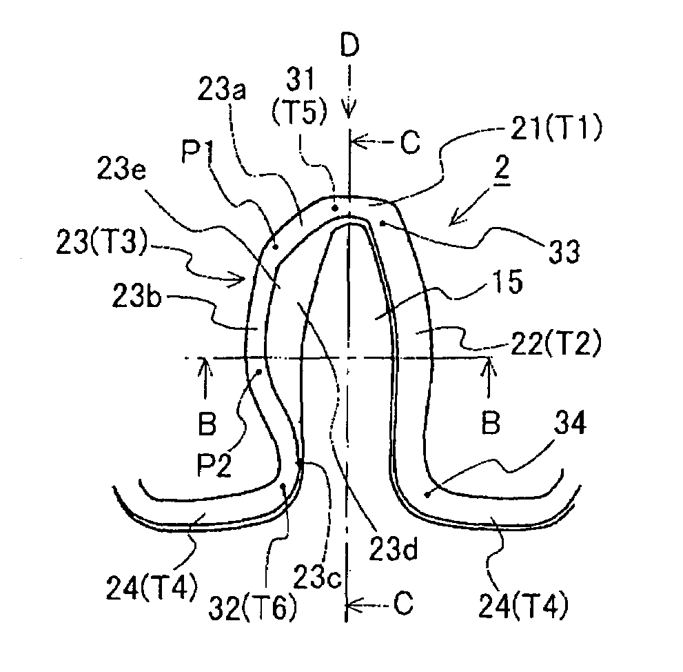
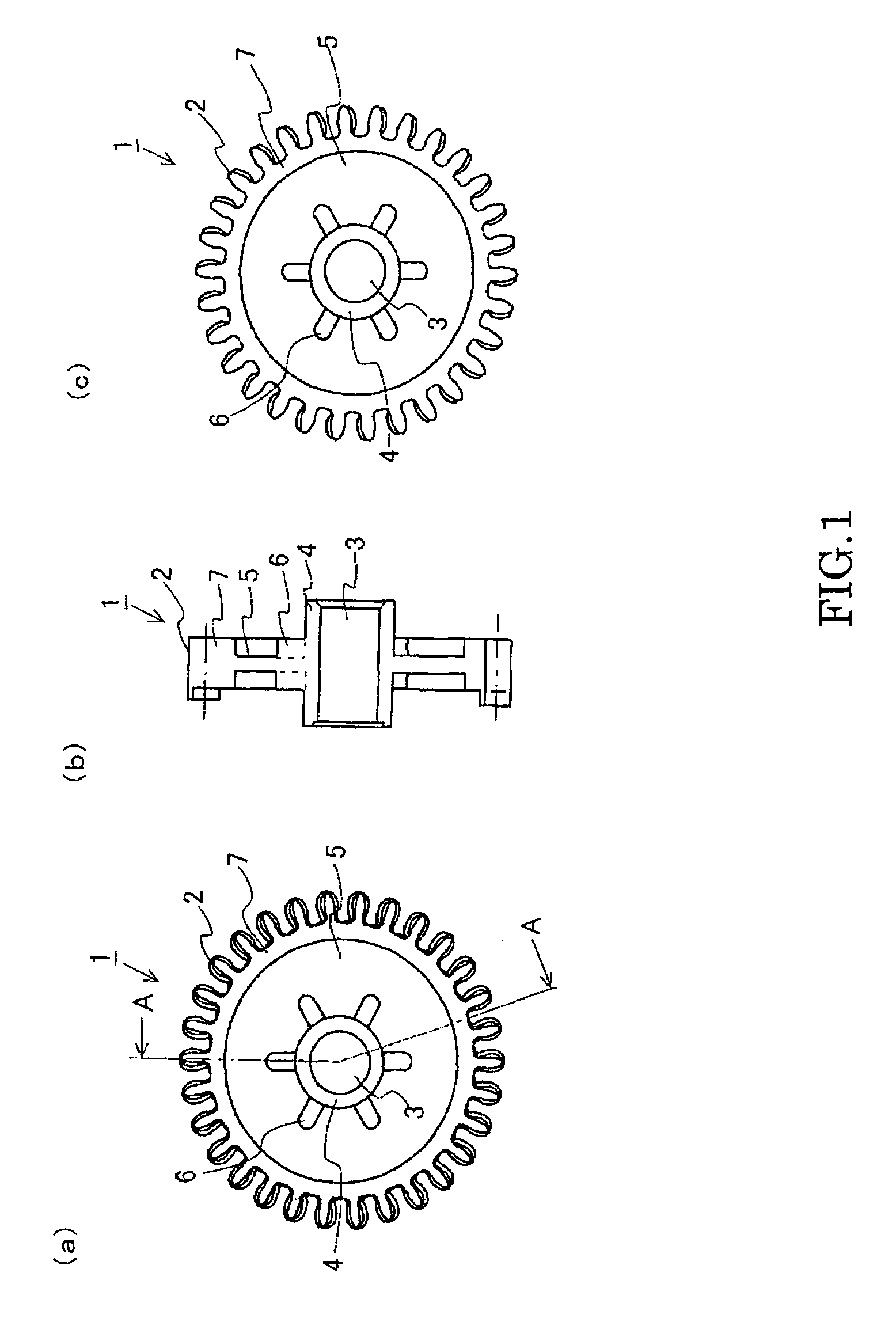
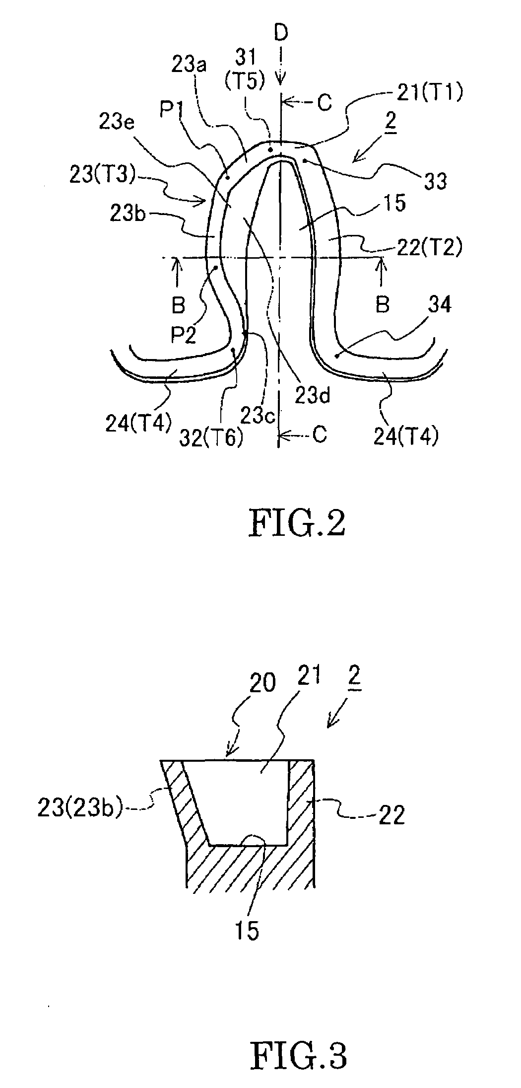
[0027]FIG. 1 to FIG. 5 are diagrams of a gear (plastic gear) 1 according to an embodiment of the present invention. FIG. 1A is a front view of a plastic gear 1. FIG. 1B is cross-sectional diagram taken along line A-A in FIG. 1A. FIG. 1C is a rear view of the plastic gear 1. FIG. 2 is an enlarged explanatory diagram of a tooth 2 of the plastic gear 1, viewed from the front side. FIG. 3 is a cross-sectional diagram of the tooth 2 taken along line B-B in FIG. 2. FIG. 4 is an enlarged cross-sectional diagram of the tooth 2 taken along line C-C in FIG. 2. FIG. 5 is an enlarged planar view of teeth 2 viewed from the direction of an arrow D in FIG. 2.

[0028]The plastic gear 1 shown in FIG. 1 to FIG. 5 according to the embodiment is a spur gear formed by injection-molding using resin material, such as polyacetal, polyamide, polyphenylene sulfide, and polybutylene terephthalate.

[0029]As shown in FIGS. 1A to 1C, a boss section 4 is disposed in the center of the plastic gear 1 in the radial dir...

second embodiment

[0049]According to the first embodiment described above, an example in which the thin-walled section 20 includes the tooth crest corresponding section 21, the tooth flank corresponding section 22, the overhanging section 23, and the bottom land corresponding section 24 that are formed consecutively is explained. The invention is not limited thereto. For example, a configuration is included in which the thin-walled section 20 does not include the tooth flank corresponding section 22 and the bottom land corresponding section 24 and is configured by the tooth crest corresponding section 21 and the overhanging section 23 that are alternating and consecutive. However, in this case as well, the thickness T1 of the tooth crest corresponding section 21 and the thickness T3 of the overhanging section 23 are set so as to fulfill the following between T1 and T3:


PUM


Abstract

A gear having a thin-walled section formed on one end face among two end faces of a tooth in a tooth-width direction is provided. A portion of the thin-walled section is projected and formed so as to serve as an overhanging section. The overhanging section prevents backlash. A thickness T3 of the overhanging section, a thickness T2 of a tooth flank corresponding section, and a thickness T1 of a tooth crest corresponding section positioned therebetween satisfies the relation T1<T3<T2.

Description

BACKGROUND OF THE INVENTION[0001]1. Field of the Invention[0002]The present invention relates to a gear structured to reduce backlash.[0003]2. Description of the Related Art[0004]Compared to a metal gear, a plastic gear has operational advantages such as being light in weight, being self-lubricating, thereby allowing use without a lubricant, and having low noise. At the same time, the plastic gear has manufacturing advantages such as allowing high productivity and allowing mass-production, thereby allowing a reduction in manufacturing costs. In recent years, the plastic gear having such advantages has been widely used in, for example, gear trains in ink-jet printers, power transmission sections of automobiles, and gear trains in precision machinery. The range of use of the plastic gear is expanding.[0005]Even in the plastic gear having low noise, as described above, teeth-knocking noises (undesirable noises) frequently occur depending on usage methods, causing undesirable noises. Fo...

Claims


Application Information

Patent Timeline
Patent Type & Authority Patents(United States)
IPC IPC(8): F16H55/14
CPCF16H55/16F16H55/18Y10T74/19967Y10T74/19907Y10T74/19963Y10T74/19972
Inventor KASHIMURA, NORITAKE
Owner ENPLAS CORP
Why Eureka
Try Eureka