Start safety ignition system

a safety ignition and ignition system technology, applied in the direction of ignition safety means, machines/engines, engine starters, etc., can solve the problems of high cost, failure, and failure of mechanical switches, and the operation of mechanical switches is not reliabl

Active Publication Date: 2010-04-20
HUSQVARNA AB
View PDF10 Cites 46 Cited by
  • Summary
  • Abstract
  • Description
  • Claims
  • Application Information

AI Technical Summary

Problems solved by technology

Since the operating tool is often close-by the operator, there is a risk of contact and an accidental injury occurring.
This can present a risk because the operator will not always be holding the machine in such a way that the security arrangements provide the intended protection.
One problem with this solution is that it operates using a mechanical switch.
This means that in case of switch failure, the arrangement will either continuously be in a speed limiting stage or never activate the speed limitation during start-up.
Another problem is that the switch, to prevent failure, has to be very reliable and therefore is expensive.
A further problem is that the switch cooperates mechanically with the start position knob on the machine and consequently relies on operator manipulation in order to be active during start-up.
The switch is activated when activating the start position knob, and if the machine is started with half or wide open throttle valve without activating the knob, the start security system will fail to perform as intended.
Still another problem is that the design of each mechanical switch is highly dependent upon the product into which it is being incorporated since the switch must cooperate and coexist with other physical components of the including machine.

Method used


Image

  • Start safety ignition system
  • Start safety ignition system
  • Start safety ignition system

Examples


Embodiment Construction

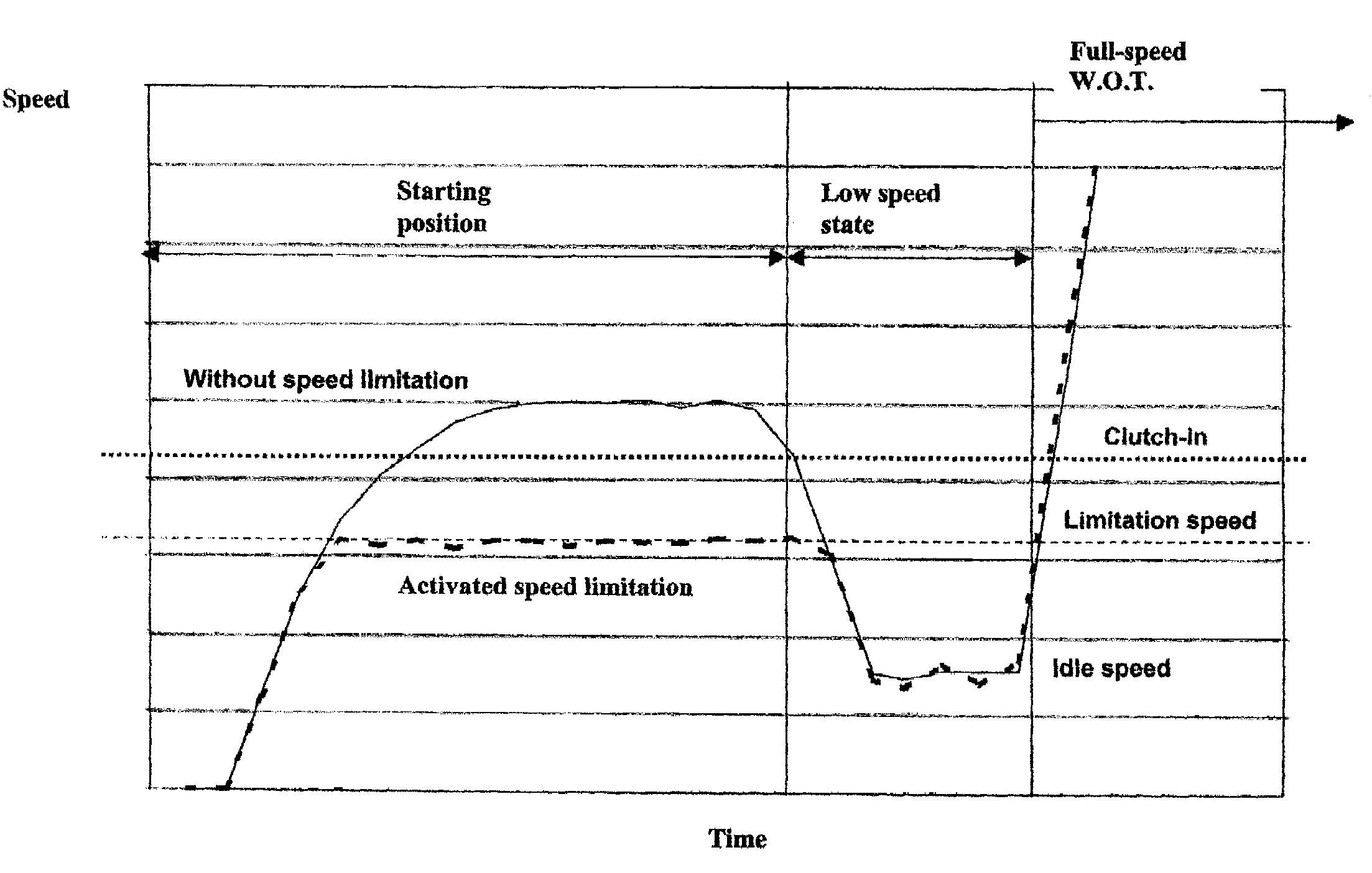
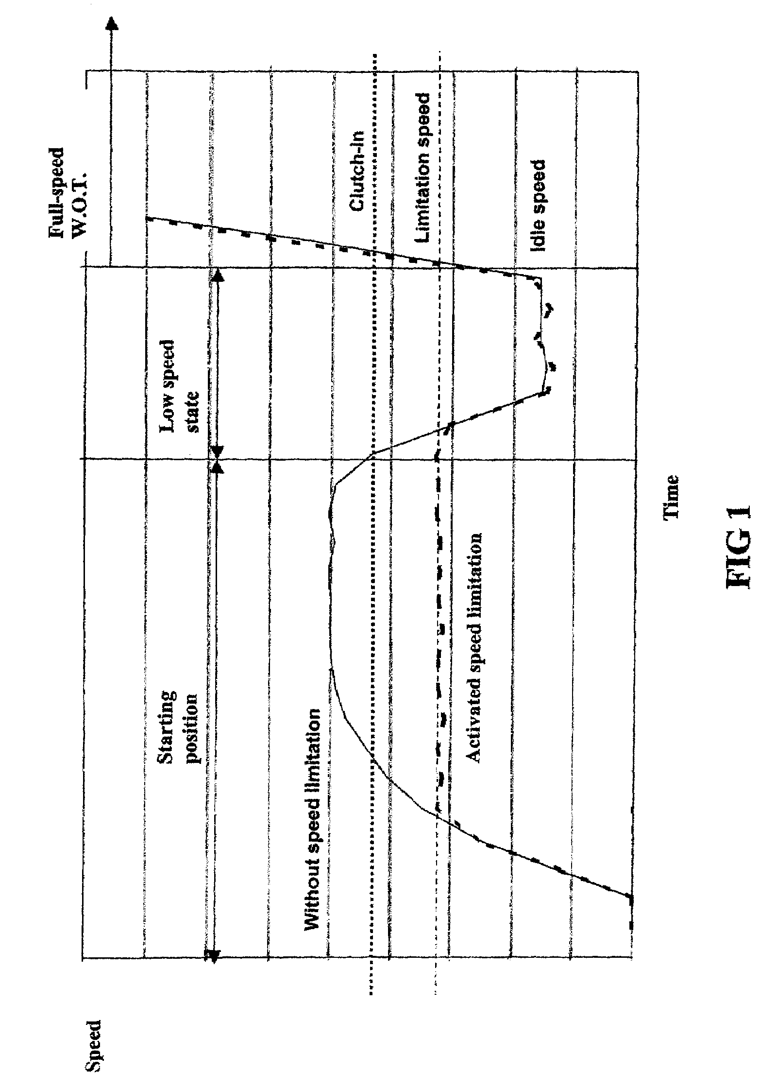
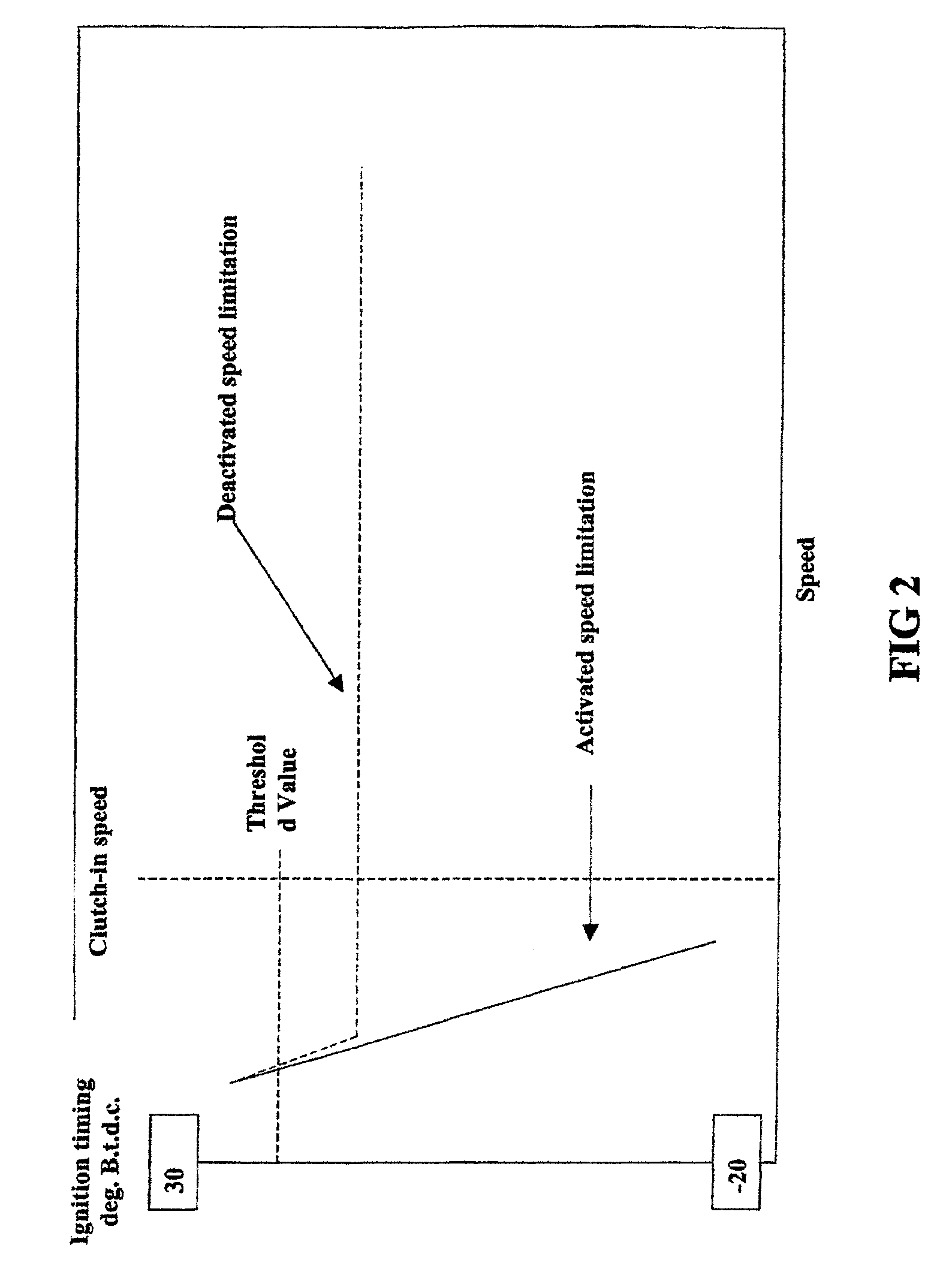
[0013]The figures show an illustrative embodiment of a method for providing a speed limitation control in accordance with the present invention. The illustrative embodiments shall not be interpreted as a limitation of the invention. The purpose is instead to illustrate how the invention can be applied and to further illustrate the scope of the claimed invention.

[0014]The illustrative embodiment relates to a microcomputer-controlled method for providing a speed limitation control in the combustion engine ignition system that has a primary firing pulse generator for charging a capacitor and an electronic switch for discharging the capacitor via an ignition coil to generate an ignition voltage. The ignition system also includes a microcomputer that operates the switch to control ignition timing of the generator.

[0015]The microcomputer, via the speed detection means, detects the rotational speed of the engine. Within the scope of the invention every speed detection means is considered, ...


PUM


Abstract

A method for controlling an ignition system of an internal combustion engine having a primary firing pulse generator for charging a capacitor. An electronic switch is included for discharging the capacitor via an ignition coil to generate an ignition voltage. A microcomputer operates the switch to control the ignition timing of the generator. The microcomputer is in communication with a speed sensor that detects the rotational speed of the engine and a speed limitation control that limits the engine speed to a limitation speed below the clutch-in speed of an included centrifugal clutch. The speed limitation control is active or activated when one of either starting the engine or an operating problem of the power tool is detected. The speed limitation control is deactivated when a low speed state of the engine is detected.

Description

CROSS-REFERENCE TO RELATED APPLICATION[0001]This application is a continuation-in-part patent application of International Application No. PCT / SE2005 / 001100 filed 1 Jul. 2005, now abandoned, which was published in English pursuant to Article 21(2) of the Patent Cooperation Treaty. Said application is expressly incorporated herein by reference in its entirety.TECHNICAL FIELD[0002]The present invention relates to a method and arrangement for controlling an ignition system of an internal combustion engine which has a primary firing pulse generator for charging a capacitor and also has an electronic switch for discharging the capacitor via an ignition coil to generate an ignition voltage. A microcomputer operates the switch to control the ignition timing of the generator and the microcomputer is communicatively connected with a speed detector, also referred to as detection means, that directly or indirectly detects the rotational speed of the engine. A speed limitation control is utiliz...

Claims


Application Information

Patent Timeline
Patent Type & Authority Patents(United States)
IPC IPC(8): F02P5/00F02P9/00
CPCF02P9/005F02P11/00F02N15/022F02P1/086F02P5/1508F02P5/1506
Inventor CARLSSON, BOLARSSON, MIKAELANDERSSON, LARSARONSSON, TORE
Owner HUSQVARNA AB
Why Eureka
Try Eureka