Small unmanned airborne vehicle airframe

a small, unmanned technology, applied in the field of unmanned aerial vehicles, can solve the problems of limited various operating parameters and typical cost of uavs, and achieve the effect of improving the overall strength of the structur

Inactive Publication Date: 2010-04-20
LOCKHEED MARTIN CORP
View PDF23 Cites 41 Cited by
  • Summary
  • Abstract
  • Description
  • Claims
  • Application Information

AI Technical Summary

Benefits of technology

[0008]The present invention is directed to a small unmanned aerial vehicle (UAV) designed for low-speed, low altitude, long endurance missions typical to UAVs of this size and class. The UAV main wing and tail wing sections, in one embodiment, are constructed of molded STYROFOAM® (polystyrene foam) and laminated over with aircraft grade thin veneer Baltic birch plywood sheets to provide the requisite wing section strength. The fuselage, in one embodiment, is constructed of a molded composite comprising a honeycomb core surrounded on one side by a layer of carbon / aramid and surrounded on the other side by a layer of carbon / aramid and a layer of fiberglass. Although a carbon / aramid layer is employed, a carbon fiber KEVLAR® (para-aramid synthetic fiber) layer is even more preferred to enhance the overall strength of the structure. The fuselage may optionally employ one or more chine structures to aid the UAV maneuverability during its flight.
[0010]The low-speed, low altitude, high endurance UAV is constructed to be quickly and easily assembled and dissembled. The main wings and the tail wing section, for example, may be attached and detached to the fuselage for ease of transport. This allows the type and composition of the wings to be changed out in order to meet the needs of a particular mission. Since the wings are easily interchangeable, and since the wings are constructed of inexpensive and easily obtainable resources, the overall cost of the UAV is substantially reduced below that necessary to provide a one size fits all type of design.
[0013]Accordingly, one aspect of the invention comprises providing a UAV having an airframe that is substantially impervious to small arms fire. Small arms fire will simply pass through the wing portions that comprise most of the air frame, leaving one or more small holes that will not substantially affect the path or flight worthiness of the UAV. A substantial portion (approximately 95%), of the UAV then, will not feel the full impact of any small arms fire. Other portions of the air frame are constructed similar to a bullet proof vest, such that small arms fire cannot penetrate the fuselage and damage any associated onboard control electronics or data collection and data communication systems.
[0015]Accordingly, a feature of the UAV includes survivability features uniquely adapted to substantially eradicate the dangers generally associated with small arms fire.
[0017]Yet another feature of the UAV includes the provision of an airframe that is modular such that the main wings and the entire tail wing assembly can be dissembled from the fuselage for ease of manual transport.

Problems solved by technology

These UAVs are typically costly and have somewhat limited various operating parameters, including but not limited to, mission modularity, portability and survivability.

Method used


Image

  • Small unmanned airborne vehicle airframe
  • Small unmanned airborne vehicle airframe
  • Small unmanned airborne vehicle airframe

Examples


Embodiment Construction

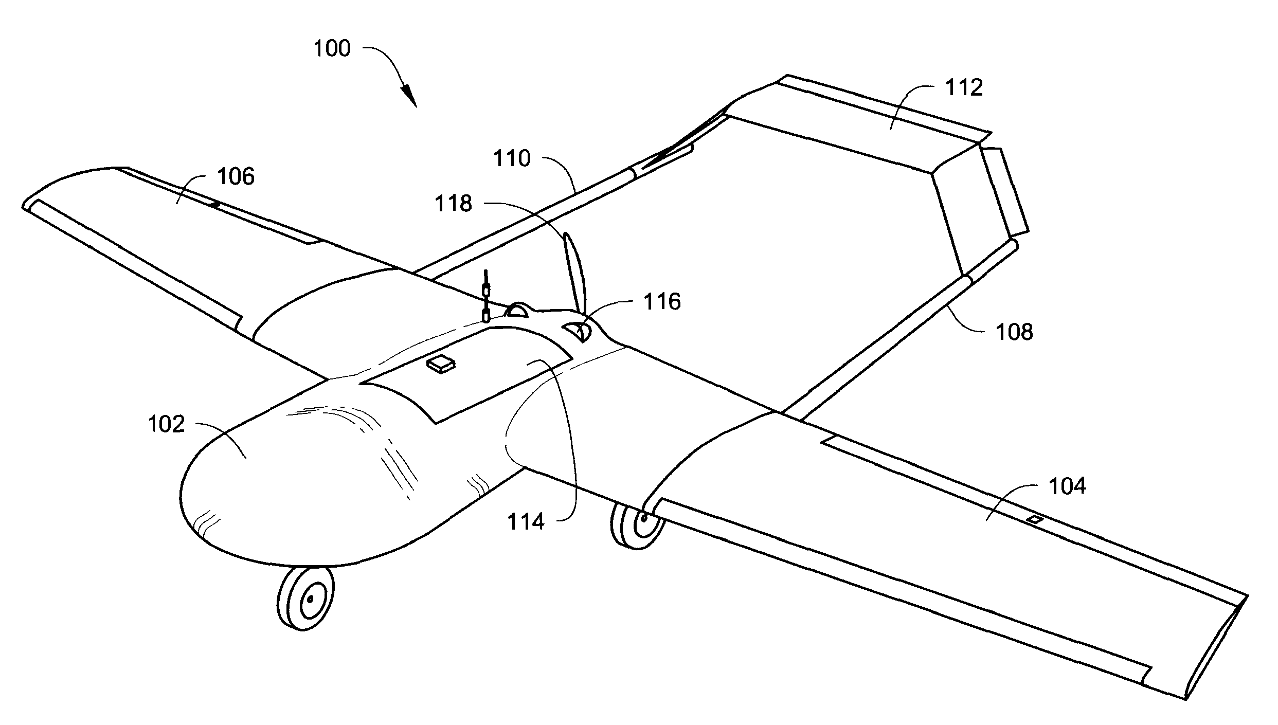
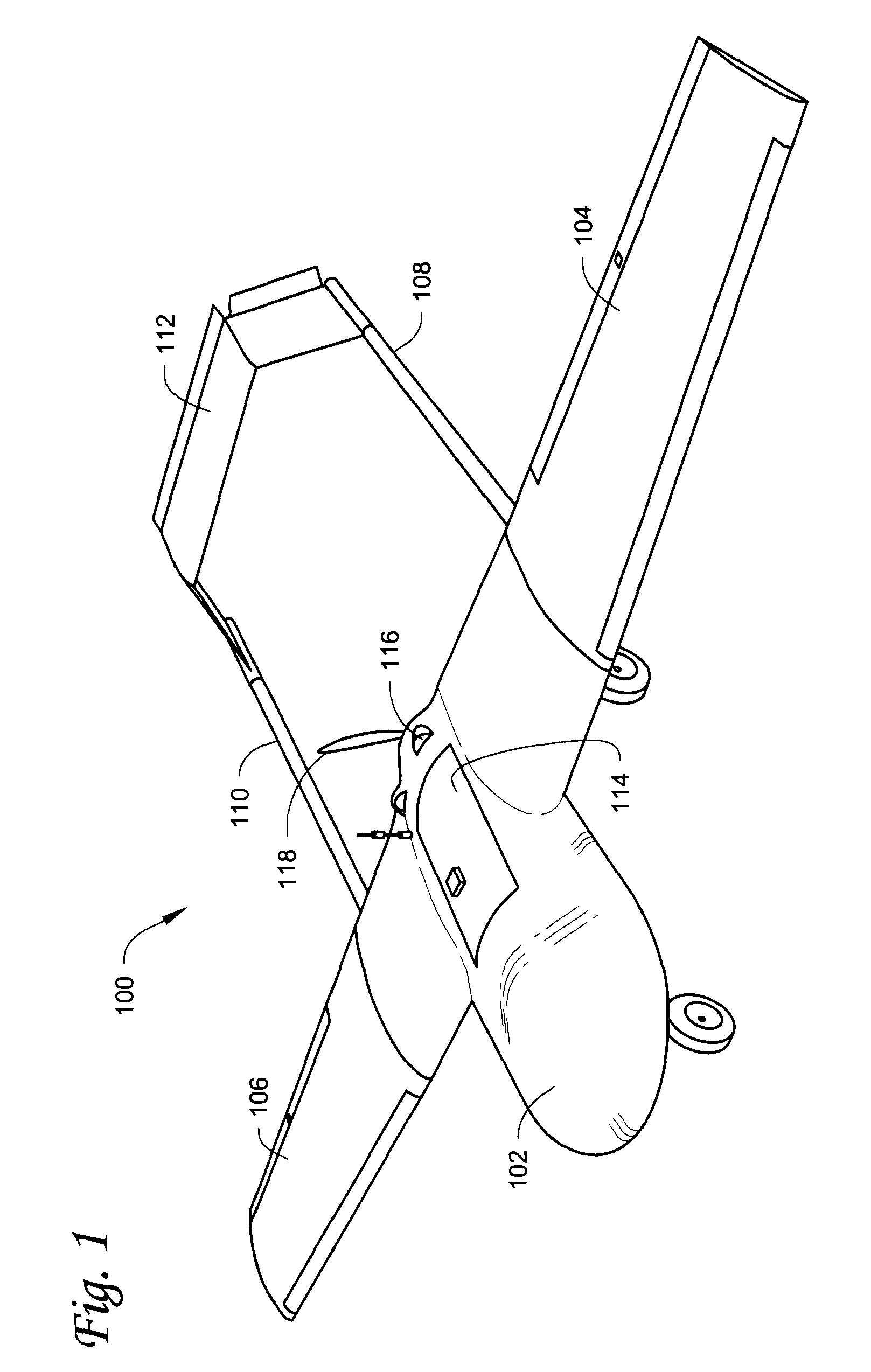
[0034]Looking now at FIG. 1, a frontal perspective view of an unmanned aerial vehicle (UAV) 100 is illustrated in accordance with one embodiment of the present invention. The UAV 100 is generally comprised of a fuselage 102, a left main wing 104, a right main wing 106, a left tail boom 108, a right tail boom 110, and a tail wing 112. The fuselage 102 is configured to carry a payload having access through an upper fuselage panel 114 that can be configured to be opened or removed as desired. The UAV 100 is powered via a rear mounted gasoline engine 116 that is configured to operate a propeller 118. The UAV 100 most preferably is small enough to be manually transported in either its fully assembled mode or in its modular break-down mode. The UAV 100 is most preferably modular such that each of the major units 102, 104, 106, 108, 110 and 112 referenced herein before is removable and replaceable independent of the other units, and may be optimized to particular performance requirements o...


PUM


Abstract

An unmanned aerial vehicle (UAV) is designed for low-speed, low altitude, long endurance missions typical to UAVs of this size and class. The UAV structure is configured to be substantially impervious to small arms fire and to have a very small representative radar cross-section. The UAV is modular such that the main wings and tail wing assembly are quickly and easily, detached from the fuselage for ease of transport and to provide an airframe that is quickly and easily adapted to any particular mission.

Description

BACKGROUND OF THE INVENTION[0001]1. Field of the Invention[0002]This invention relates generally to unmanned aerial vehicles (UAVs), and more particularly to unmanned aerial vehicles designed for low-speed, low altitude, long endurance missions typical to UAVs of this size and class (sometimes called MALE UAVs).[0003]2. Description of the Prior Art[0004]Particular military and civil emergency environments sometimes require aerial response capabilities. One example might be a rescue at sea environment in which aerial sensing, targeting, detection and communication capability can directly or indirectly aid persons in peril. Time sensitive emergency operations in particular require highly accurate aerial sensing and data transmission, delivered preferably via highly mobile, man-portable, GPS-referenced, flexible aerial platforms capable of rapidly launching various payloads and sensors, and being readily adaptable to changes in mission objectives and payload requirements.[0005]Surveill...

Claims


Application Information

Patent Timeline
Patent Type & Authority Patents(United States)
IPC IPC(8): B64C39/00
CPCB64C39/024B64C2201/021B64C2211/00B64U10/25B64U50/11B64U30/10B64U60/50
Inventor COLTEN, TODD M.MORGAN, SCOTT E.LAUNER, CHRISTOPHER A.
Owner LOCKHEED MARTIN CORP
Why Eureka
Try Eureka