Common bus aircraft retrofit load control

a common bus and load control technology, applied in the field of electric energy conveyance art, can solve the problems of significant difficulty in rework, significant work and expense involved in rework, and difficulty in rewiring an aircraft, etc., and achieve the effect of special desirable utility

Inactive Publication Date: 2010-04-20
AIR FORCE UNITED STATES OF AMERICA AS REPRESENTED BY THE SEC OF THE THE
View PDF15 Cites 14 Cited by
  • Summary
  • Abstract
  • Description
  • Claims
  • Application Information

AI Technical Summary

Benefits of technology

[0021]It is another object of the invention to provide a common bus remote load control arrangement having especially desirable utility in a large aircraft setting.

Problems solved by technology

A “smart” ability to accomplish this new function can often save significant amounts of work and expense involved in a rework effort.
A problem with this usual wiring arrangement often arises when a new or additional usage of one or more of these boxes is contemplated, a use such as providing a combination electrical light and ceiling fan is desired in the room.
When the box to box conductors are two in number, lie buried between wall surfaces and between first floor ceiling and second floor flooring and consist of flexible “Romex” or “BX” or other common two conductor residential wiring forms, the provision of a new third or additional electrical conductors for separate control of fan speed, fan direction and lamp intensities for example is a significant dilemma.
Although the Casablanca control and coding technique is elegant in design and performance it is limited by practicalities such as nearby lightning surges being often destructive of semiconductor devices when integrated into long house wiring runs, by switch contact resistance increasing over use lifetime, by generation of distorted sinusoid wave shapes (that are minimally diminished in electrical energy delivery effect but include high frequency harmonics, a possible source of radio frequency interference noise) and by the inherent applicability of the coding only to alternating current electrical energy sources.
It is for example particularly difficult to re-wire an aircraft in order to provide for new exterior or interior light sources or to energize other loads especially when such loads may necessitate physical dispositions at distant locations of a large airframe and thus require transmission of energy through hundreds of feet of integrally assembled and hidden factory installed wiring.
Re wiring is of further increased difficulty when the wiring in an originally installed factory bundle is now characterized by electrical insulation degradation such as embrittlement or chafing or where the aircraft includes decorative or thermal insulation interior panels or other physical obstructions for examples.
Aircraft rewiring is in fact so difficult and costly that the practice of “retirement in place” for original wiring has become commonplace in older aircraft, particularly in military aircraft.
For example electronic equipment at the time of B-52 design was almost totally dependent on vacuum tubes and thus was characterized by low input to output efficiency, larger physical size and greater energy usage than is now experienced with integrated circuits and other semiconductor equipment.

Method used


Image

  • Common bus aircraft retrofit load control
  • Common bus aircraft retrofit load control
  • Common bus aircraft retrofit load control

Examples


Embodiment Construction

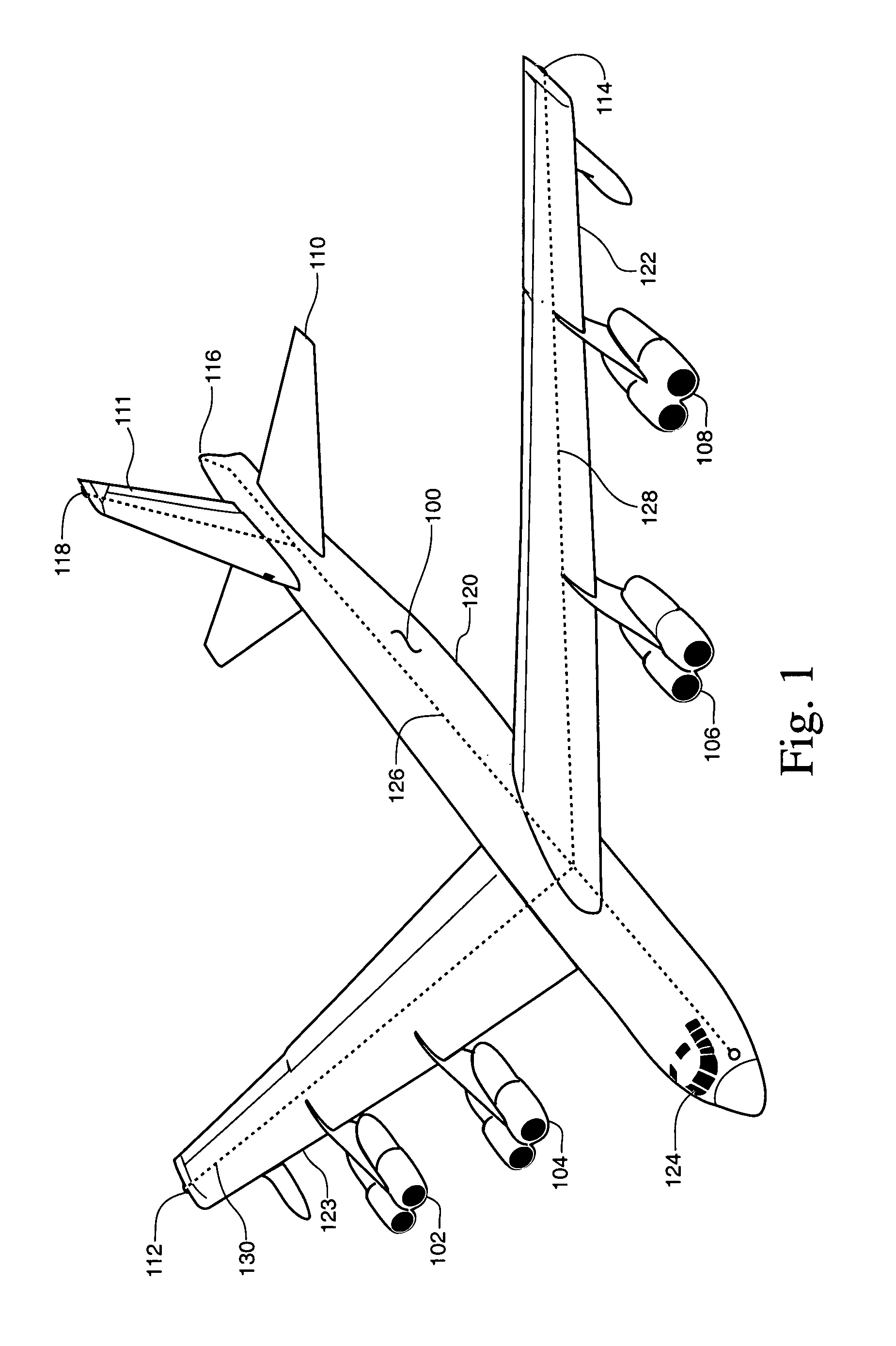
[0038]FIG. 1 in the drawings shows a representative larger size aircraft inclusive of a remote load control arrangement according to the present invention. In the FIG. 1 drawing the aircraft 100 may be considered to be a B-52 or a C-5 or a C-17 or C-130 or a C-135 or A-10 or other aircraft. This aircraft is provided with the four jet type engines 102, 104, 106 and 108, a fuselage 120, wing sections 122-123, an elevator assembly 110 and a rudder system 111, all as are conventional for such aircraft. Attached to extremities of the wings 122 and 123, the rudder system 111 and the fuselage 120 are aircraft external light source fixtures 112, 114, 116 and 118 that may serve as aircraft markers and for possible additional functions such as visual signal sources.

[0039]For present invention purposes it is assumed that an electrical bus 126 of either one single conductor plus the common fuselage ground variety or of the two individually isolated conductors variety extends from the cockpit 12...


PUM


Abstract

A retrofit energization arrangement especially suitable for an aircraft wherein original factory-placed wiring can be reused in common bus form for plural new loads in order to avoid the expense and hazard of disassembling original wiring bundles for new conductor incorporation. Serviceable wiring possibly earlier retired in place or becoming unneeded from equipment removal can, by way of the invention, be used for plural diverse new loads including loads of disparate operating cycle and current requirements for example, even though energized via a common bus. In the disclosed apparatus both energizing current and load control signals are transmitted via the same electrical bus between control location and load areas of the aircraft where control decoding and energy tap-off occur, the latter by switch mode power supply if needed. Control signals of sinusoidal waveform, minimal electromagnetic and radio frequency interference character and limited existing bus filtering attenuation are disclosed; these may be embodied as the Frequency Shift Keying (FSK) or Continuous Tone Coded Squelch System, CTCSS, frequencies used in the radio communication art. Loads of differing types are disclosed as examples in the described embodiment of the invention; additional loads are feasible. Use of the invention in land vehicles, watercraft and building structures is also contemplated.

Description

RIGHTS OF THE GOVERNMENT[0001]The invention described herein may be manufactured and used by or for the Government of the United States for all governmental purposes without the payment of any royalty.BACKGROUND OF THE INVENTION[0002]In the electrical energy conveyance art there is often a need to use existing inaccessible electrical wiring in order to achieve some new and originally unconsidered function. A “smart” ability to accomplish this new function can often save significant amounts of work and expense involved in a rework effort. This set of events is encountered in a plurality of differing applications of the electrical arts, i.e., in numerous fields of endeavor including buildings and transportation equipment of differing types.[0003]One example of this situation is to be found in the electrical wiring of certain rooms in many homes especially in the United States but also other locations of the world. In these rooms, such as in a bedroom, there is originally provided a ce...

Claims


Application Information

Patent Timeline
Patent Type & Authority Patents(United States)
IPC IPC(8): B60L1/00B60L3/00H02G3/00
CPCH04B3/548H02J13/0003Y02T90/16H04B2203/5445B64D2221/00H04B2203/5416H02J2310/44H02J13/00016
Inventor JOHNSON, SCOTT V.MARTIN, JOHN J.
Owner AIR FORCE UNITED STATES OF AMERICA AS REPRESENTED BY THE SEC OF THE THE
Why Eureka
Try Eureka