
X-ray security inspection machine

Inactive Publication Date: 2010-04-20
RAPISCAN SYST LTD
View PDF137 Cites 17 Cited by
  • Summary
  • Abstract
  • Description
  • Claims
  • Application Information

AI Technical Summary

Benefits of technology

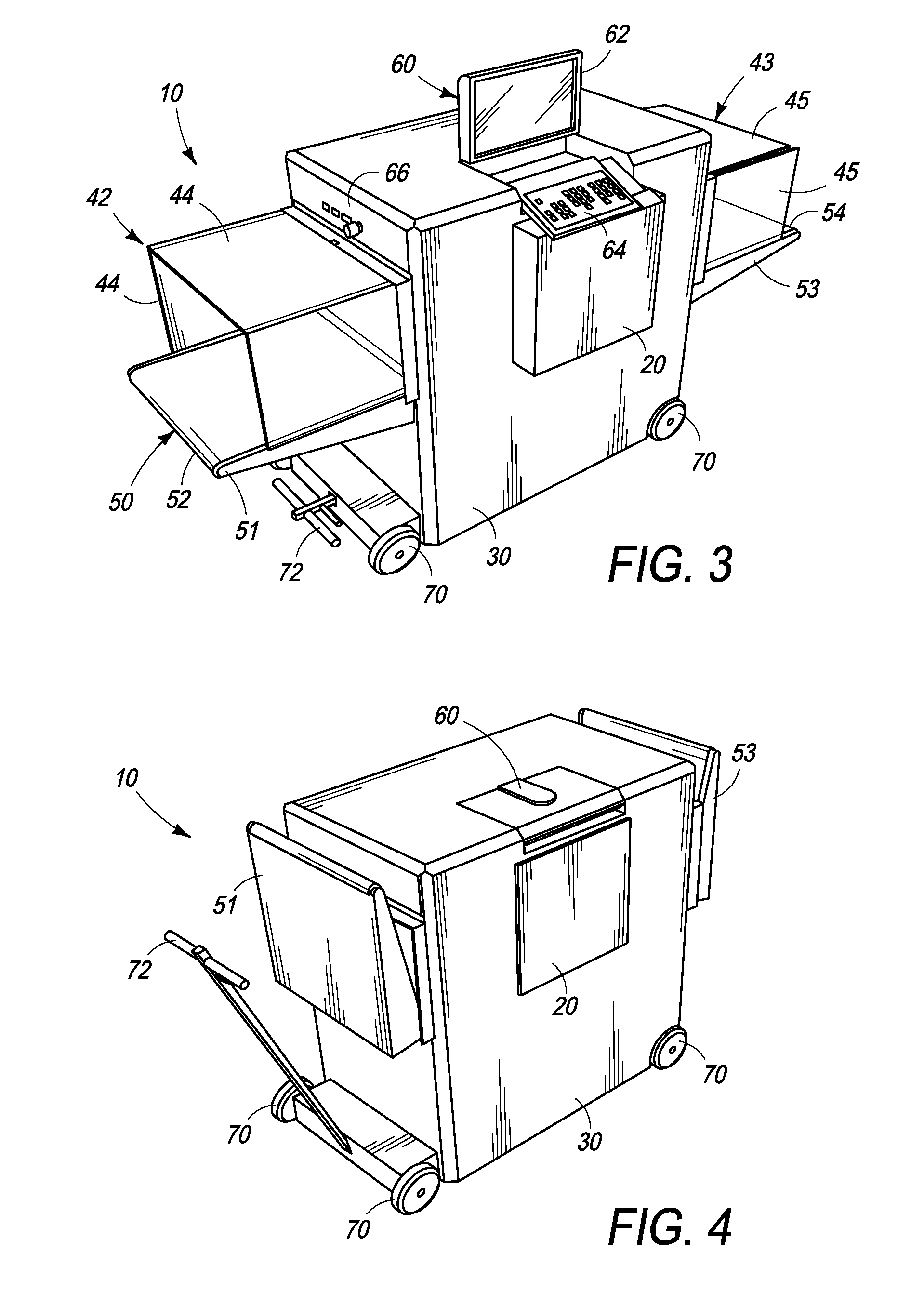
[0009]The provision of a photodetector array module which may be moved between a stowed configuration and a deployed configuration has the advantage of reducing the width of the machine when not in use, thereby facilitating movement of the machine between locations of use, especially in space-restricted environments. What is more, because the photodetector array module may be actuated to a deployed, operational position, the dimensions of the tunnel opening of the machine are to some extent independent of the overall width of the machine when configured for relocation. For previous X-ray security inspection machines, the overall width of the machines is a function of the tunnel opening width and the width of the housing which surrounds the opening, containing control and detection electronics, power and control cables, and X-ray shielding material etc. The photodetector arrays of these machines are fixed assemblies on the general housing frameworks of the machines. Thus it has been commonly held that, in order to provide a machine width of less than a standard doorway (765 mm), a correspondingly smaller tunnel opening is necessary. In particular, it has not been possible previously to achieve an X-ray security inspection machine having a standard tunnel opening of 640 mm by 430 mm while also having a width of less 765 mm, preferably having a width of 735 mm.
[0022]Of course, when the two units overlap, the width of the X-ray detection means is reduced. In this way, the same advantages discussed above are achievable, since the units may be arranged to overlap when the machine is not in use—thereby providing a more compact machine profile for manoeuvrability in confined areas—and to move apart from each other to reduce the degree of overlap when set up for use—thereby providing an X-ray detection area and corresponding tunnel size of greater size, particularly of the standard dimensions specified above.

Problems solved by technology

In particular, it has not been possible previously to achieve an X-ray security inspection machine having a standard tunnel opening of 640 mm by 430 mm while also having a width of less 765 mm, preferably having a width of 735 mm.

Method used


Image

  • X-ray security inspection machine
  • X-ray security inspection machine
  • X-ray security inspection machine

Examples


first embodiment

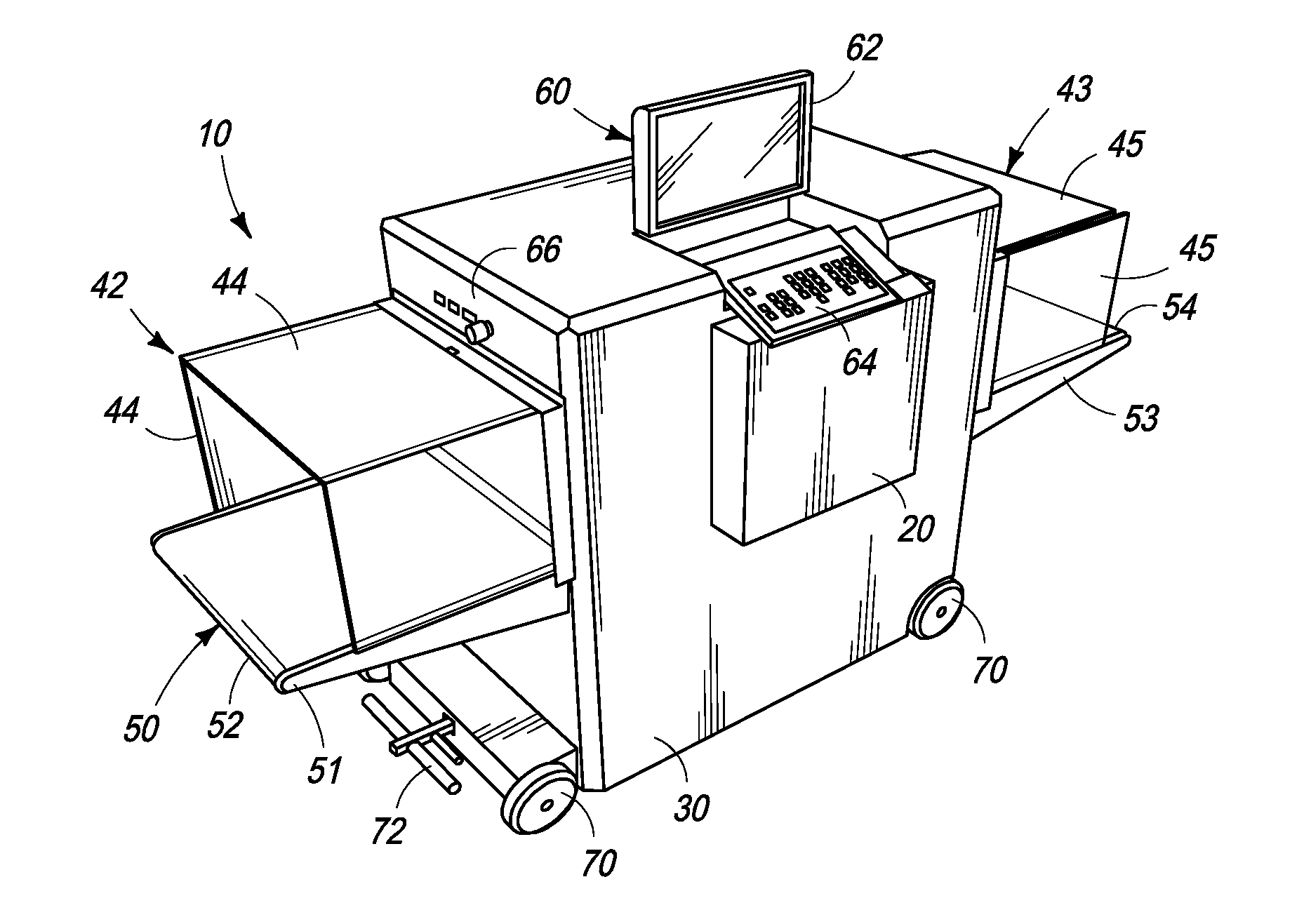
[0036]Referring to FIG. 3, there is shown an X-ray security inspection machine 10 in accordance with the invention. In this embodiment, the machine is fully deployed ready for use. A photodetector array module 20 has been extended to its deployed position and projects from the X-ray machine's housing 30. The extent of projection of the photodetector array module 20 is typically between 60 mm and 100 mm, but preferably the module extends by approximately 80 mm from the housing.

[0037]Contained within the housing 30 are the necessary components for providing an X-ray security inspection machine, including an X-ray generator, processing and control electronics, power and control cables, a computer processor and memory storing suitable operational software, and X-ray shielding material, as will be understood by the skilled person.

[0038]Above the X-ray generator (not shown) within the housing 30 and below the upper surface of the photodetector array module 20, the housing defines a tunnel...

second embodiment

[0048]FIGS. 5 to 7 illustrate the above sequence with reference to the invention. In FIG. 5, the machine 10 is in its stowed configuration suitable for transportation of the machine. In this embodiment, the control console 60 is provided as a different arrangement from the previous embodiment, and the screen 62 and keypad / mouse pad 64 are not arranged to deploy automatically, nor in concert. The monitor 62 is positioned on top of the housing 30 and is arranged to pivot between a stowed position, substantially parallel with the top surface of the housing and an operational position, substantially normal to the upper surface of the housing. The keypad / mouse pad 64 is stowed in a storage compartment 32 spaced away from the photodetector array module 20. As in the previous embodiment, the photodetector array module 20 is substantially flush with the side surface of the housing 30 when in the stowed configuration.

[0049]FIG. 6 shows the machine 10 at the stage where manual deployment of v...


PUM


Abstract

X-ray security inspection machine (10) comprising an X-ray tunnel (40); a conveyor means (50) for conveying an article through the tunnel; an X-ray source for irradiating the article; and an X-ray detection means for detecting X-rays transmitted through the article. In one aspect, the detection means comprises a photodetector array module (20) actuatable between a first stowed configuration and a second deployed configuration. In a second aspect, the detection means comprises a first unit having a first photodetector array (22); and a second unit, having a second photodetector array (24), offset with respect to the first unit. The units are moveable relative to one another between a first arrangement where the arrays overlap to a first degree and a second arrangement where they overlap to a second, lower degree; preferably zero. Also, a conveyor belt-tracking device (100) comprising a guide frame (104) to receive the conveyor belt (116) and substantially to restrict its motion to a predetermined direction.

Description

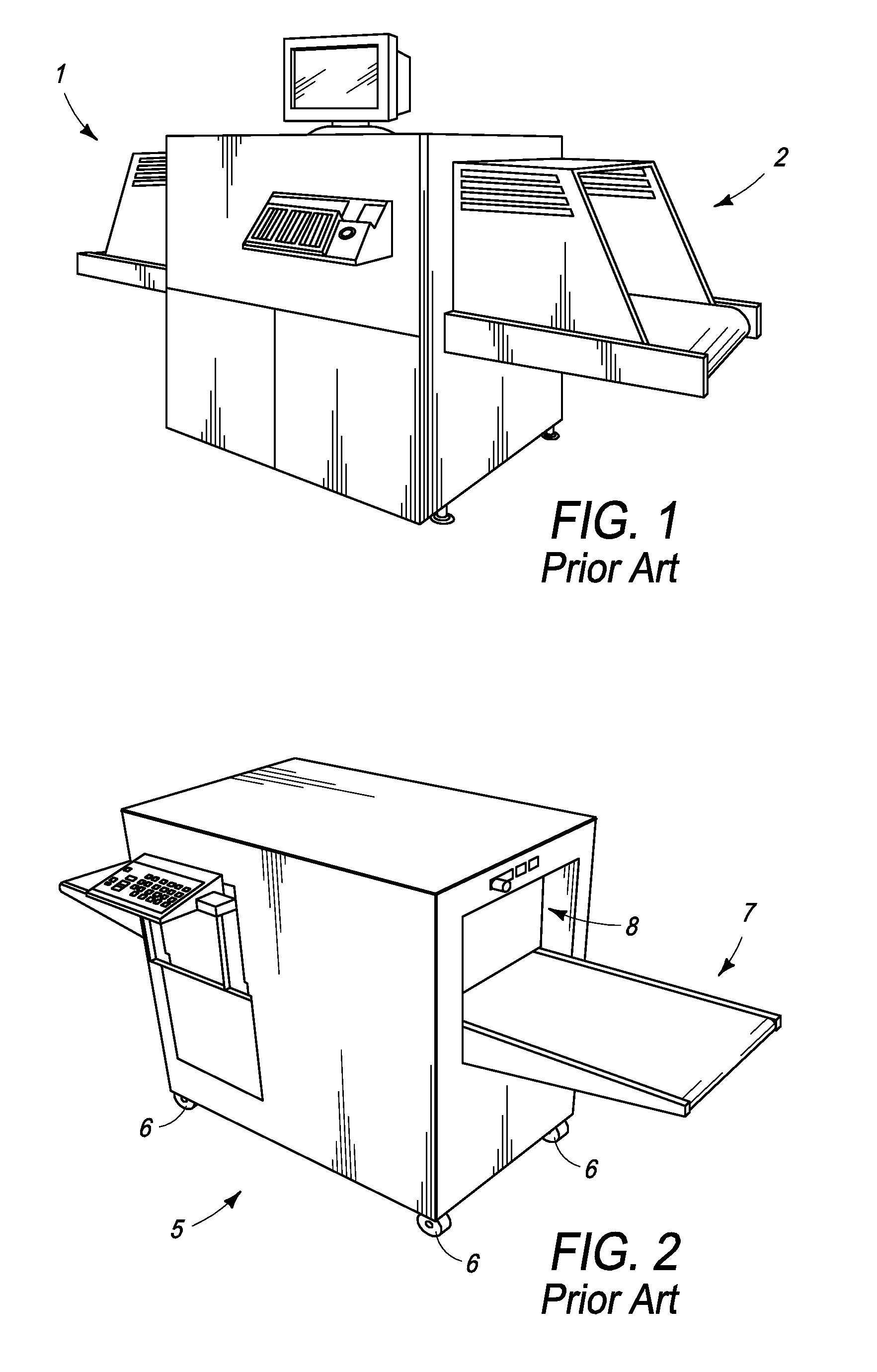
CROSS-REFERENCE[0001]The present application is a national stage application of PCT / GB2006 / 000690, having an international filing date of Feb. 27, 2006 and a priority date of Feb. 25, 2005.BACKGROUND OF THE INVENTION[0002]The invention relates to an X-ray security inspection machine, in particular an X-ray security inspection machine having a compact profile.[0003]X-ray security inspection machines are widely used at security checkpoints, such as those in airports, courthouses, government offices, embassies, schools and prisons. Where space is not restricted or where an X-ray security inspection machine is required on a permanent basis, the machine may be set up and configured on site, and retained there indefinitely. Such machines are provided in various sizes and specifications, depending on their intended application. FIG. 1 shows a perspective view of such a prior art X-ray security inspection machine 1, manufactured as model 520B by Rapiscan Security Products Ltd, of West Susse...

Claims


Application Information

Patent Timeline
IPC IPC(8): G01N23/04G01V5/00
CPCG01V5/0016G01V5/22G01V5/00H05G1/02
Inventor PANESAR, BALJINDER SINGHGILLARD-HICKMAN, DOUGLAS R.
Owner RAPISCAN SYST LTD
Learn More