Spread spectrum in-band utility communication channel

a utility communication channel and spectrum technology, applied in the field of optical communication systems, can solve the problems of large waste of optical components needed to receive, transmit, and otherwise process optical signals, and low utility data data rate,

Inactive Publication Date: 2010-04-20
CISCO TECH INC
View PDF8 Cites 7 Cited by
  • Summary
  • Abstract
  • Description
  • Claims
  • Application Information

AI Technical Summary

Benefits of technology

[0008]Utility data modulation is superimposed on a payload data modulated optical signal by exploiting spread spectrum techniques by virtue of one embodiment of the present invention. Utility data transmission rates of e.g., 200 Kbps, can be achieved without impairment to payload data transmission. The utility data modulated signal spectrum overlaps and may be entirely within the payload data modulation spectrum, thereby overcoming problems with optical amplifier gain control and pink noise.

Problems solved by technology

This represents a tremendous waste of the optical components needed to receive, transmit, and otherwise process the optical signal because a single wavelength may well be capable of carrying, e.g., 2.5, 10, or more Gbps of payload data for which the service provider could earn revenue whereas the data rate of the utility data may be quite low.
This latter approach also carries serious drawbacks.
However, the spectrum left unoccupied by the payload data modulation is insufficient to accommodate the data rate necessary for timely transmission of firmware upgrades.
Furthermore, the low frequency of the utility data modulation may be within the loop bandwidth of optical amplifier regulation along the link causing optical amplifier gain to undesirably vary in response to the utility data stream.
Also, if the flow of payload data ceases for some reason, the optical signal may be subject to superimposed pink (1 / f) noise that would swamp the baseband utility data.

Method used


Image

  • Spread spectrum in-band utility communication channel
  • Spread spectrum in-band utility communication channel
  • Spread spectrum in-band utility communication channel

Examples


Embodiment Construction

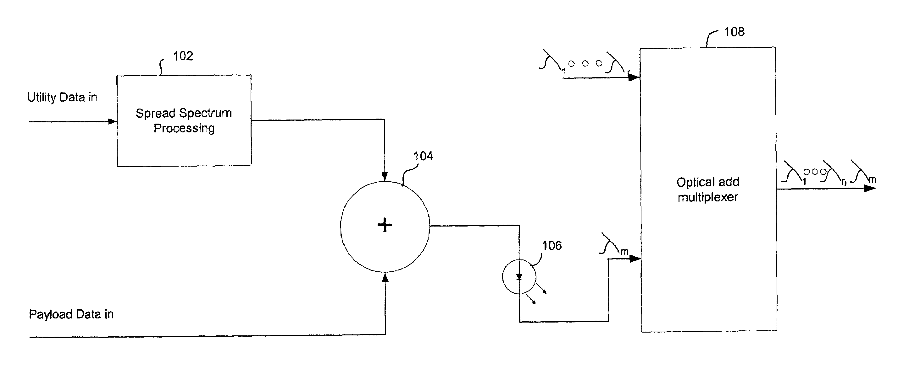
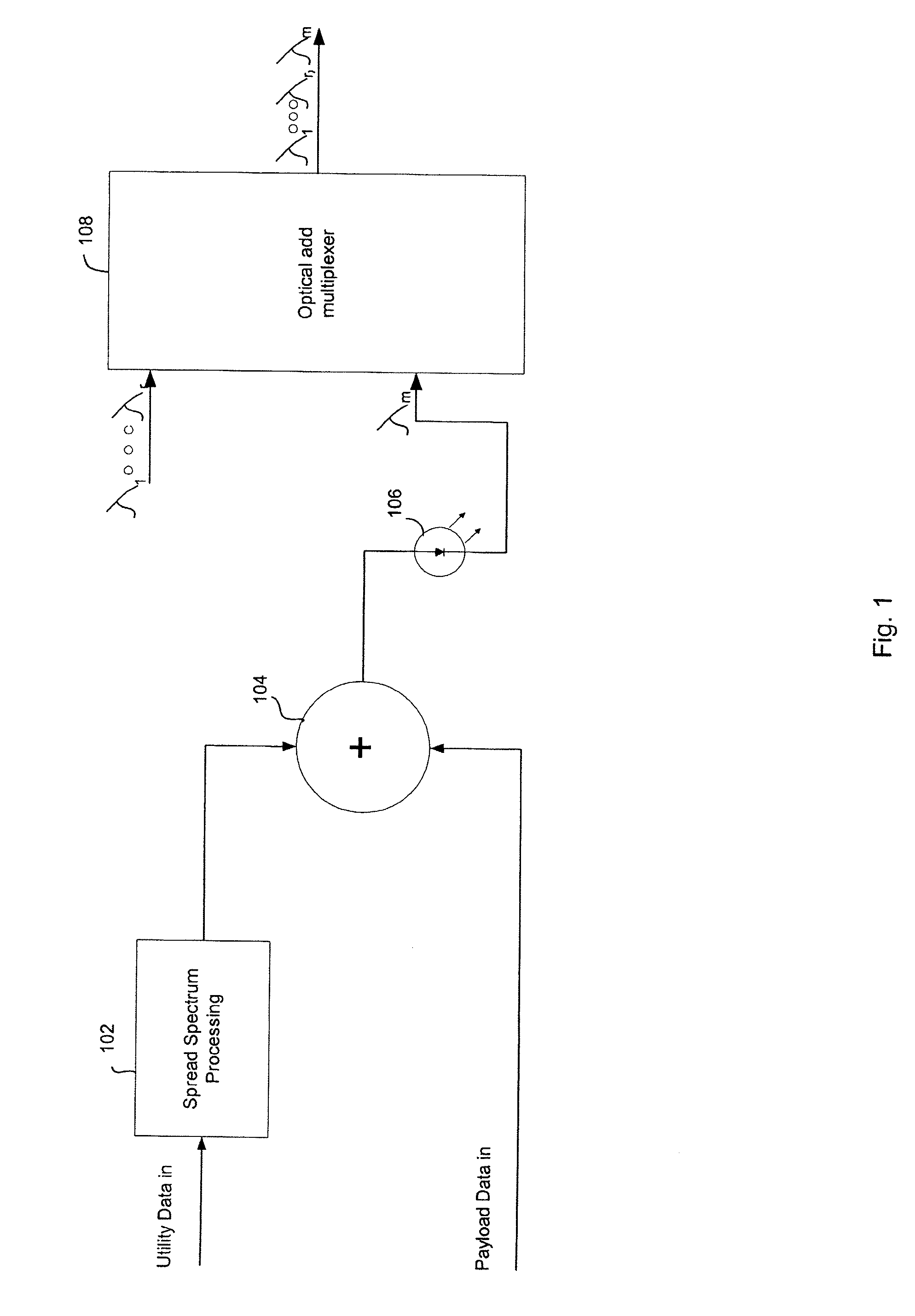
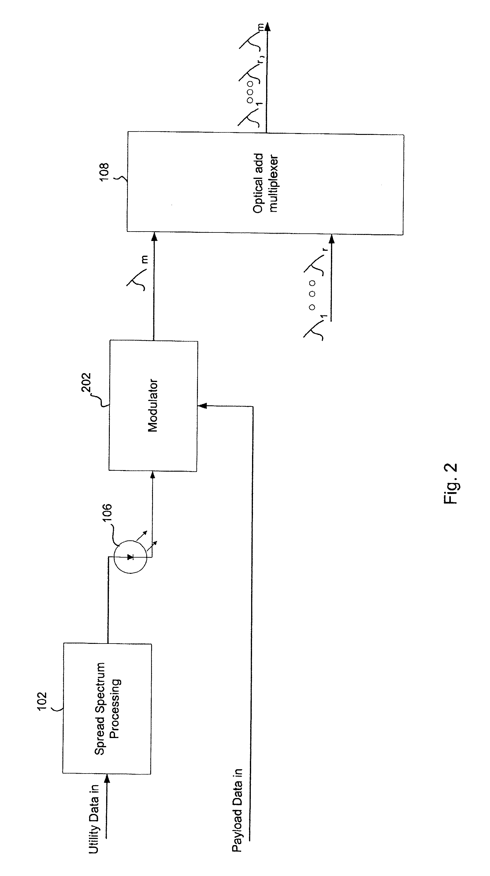
[0020]The present invention will now be described with reference to an example optical communication system employing wavelength division multiplexing (WDM) techniques wherein multiple optical signals having disparate wavelengths are combined on a single fiber. At least one of the wavelengths is allocated for communication of both payload data and utility data. Utility data pertains to operation of the network itself rather than to the services provided by the network. Examples of utility data include optical signal strength information pertaining to various points of the network, environmental parameters including temperature, firmware code for updating communication equipment forming a part of the network, etc.

[0021]The present invention will be described with reference to a node capable of transmitting and / or receiving payload and utility data on the same wavelength. The node may be connected in a ring with other nodes. This application is merely representative and the present in...


PUM


Abstract

Utility data modulation is superimposed on a payload data modulator optical signal by exploiting spread spectrum techniques by virtue of one embodiment of the present invention. Utility data transmission rates of e.g., 200 Kbps, can be achieved without impairment to payload data transmission. The utility data modulated signal spectrum overlaps or is entirely within the payload data modulation spectrum, therefore, overcoming problems with optical amplifier gain control and pink noise.

Description

CROSS REFERENCE TO RELATED APPLICATIONS[0001]This application is a continuation of U.S. patent application Ser. No. 09 / 931,073 filed Aug. 15, 2001, entitled “Spread Spectrum In-Band Communication Channel,” the entire contents of which are hereby incorporated by reference.BACKGROUND OF THE INVENTION[0002]The present invention relates to optical communication systems and more particularly to systems and methods for communicating management information via optical links.[0003]The explosion of communication services, ranging from video teleconferencing to electronic commerce is providing rapid growth of Internet traffic. To cope with the rising volume of Internet traffic, service providers are more and more relying on optical technology both in the core network and as a way of accessing network users. To obtain a multiplicative increase in capacity, wavelength division multiplexing (WDM) techniques are being employed where multiple optical signals having disparate wavelengths share the ...

Claims


Application Information

Patent Timeline
Patent Type & Authority Patents(United States)
IPC IPC(8): H04B10/04
CPCH04B10/0773H04B2210/074
Inventor MORK, GORANMARTENSSON, JOHANWAHLBECK, DAN
Owner CISCO TECH INC
Why Eureka
Try Eureka