Object classification system for a vehicle

a classification system and vehicle technology, applied in scene recognition, pedestrian/occupant safety arrangement, instruments, etc., can solve the problems of large processing power and time required by current camera technology to compute relevant information, low processing efficiency, and large processing time requirements of current camera technology, so as to improve the classification and tracking efficiency, reduce the processing time, and reduce the processing time. , the effect of reducing the number of errors

Inactive Publication Date: 2010-04-20
FORD GLOBAL TECH LLC
View PDF7 Cites 13 Cited by
  • Summary
  • Abstract
  • Description
  • Claims
  • Application Information

AI Technical Summary

Benefits of technology

[0010]The embodiments of the present invention provide several advantages. One such advantage is the provision of a collision warning and countermeasure system that minimizes image processing time, processor requirements, memory requirements, and system complexity, thus providing a cost effective and feasible solution for in-vehicle use of existing camera technology.
[0011]Another advantage provided by an embodiment of the present invention is the provision of a method of associating data collected from both electro-magnetic and electro-optical sensors, such as radar sensors and cameras, to better and more efficiently classify and track objects.
[0012]Yet another advantage provided by an embodiment of the present invention is the provision of a collision warning and countermeasure system that utilizes registered feature functions and / or feature descriptions to classify an object. The stated embodiment provides increased object classification accuracy and efficiency.
[0013]Another advantage provided by an embodiment of the present invention is the provision of a collision warning and countermeasure system that utilizes sum-array techniques to achieve real time performance.

Problems solved by technology

Also, standard object classification systems tend to detect or generate false objects, due to the highly variable ranges of vehicles and objects.
Unfortunately, current camera technology requires a large amount of processing power and time to compute relevant information required for in-vehicle use.
For example, image processing from a charge coupled device (CCD) camera is time consuming due to the large amount of data collected for each image, approximately 640×480 pixels per frame at 30 frames per second.

Method used


Image

  • Object classification system for a vehicle
  • Object classification system for a vehicle
  • Object classification system for a vehicle

Examples


Embodiment Construction

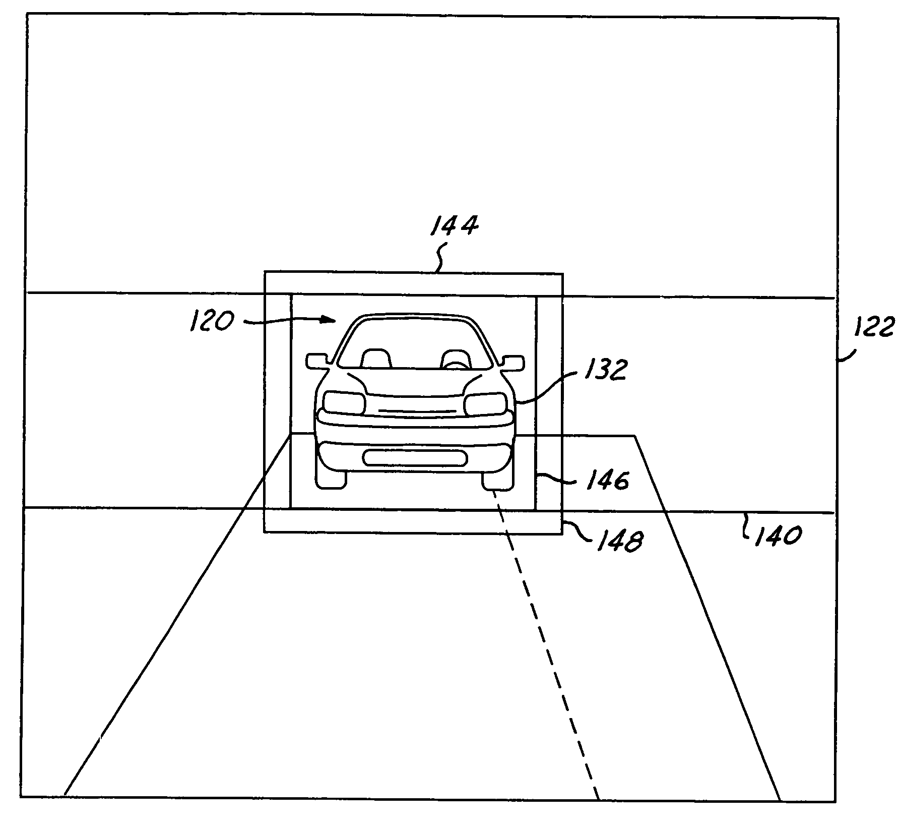
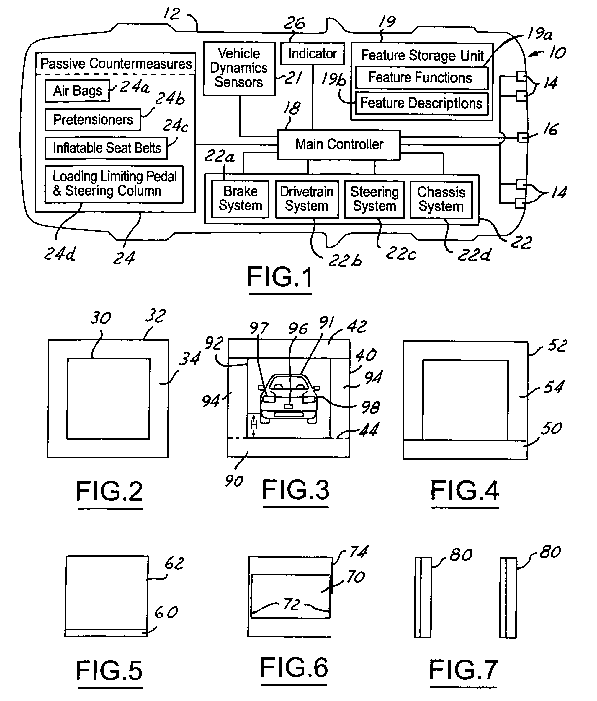
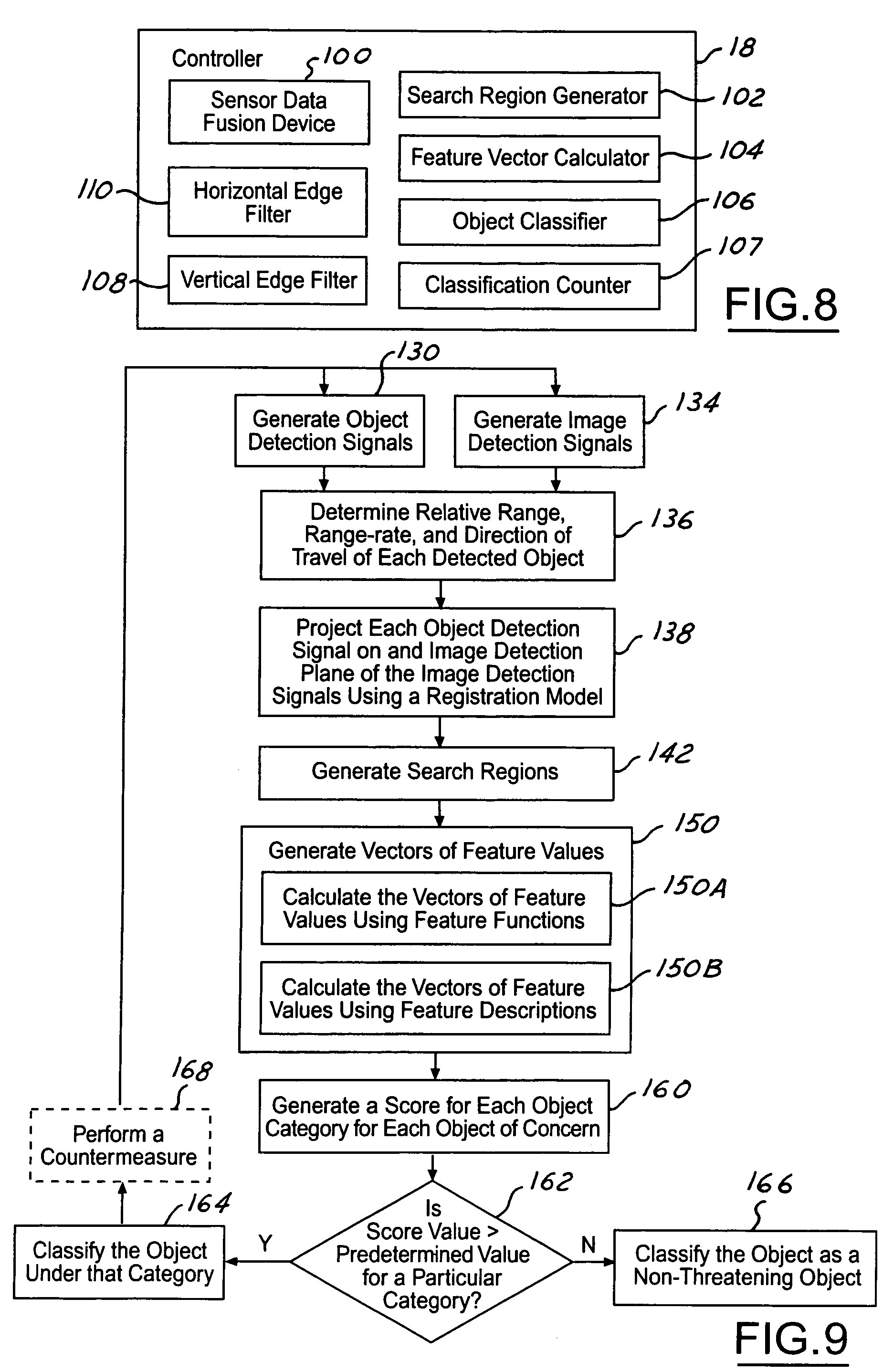
[0028]In the following Figures the same reference numerals will be used to refer to the same components. While the present invention is described with respect to system and method of classifying detected objects for collision warning and countermeasure performance, the present invention may be adapted and applied to various systems including: collision warning systems, collision avoidance systems, parking aid systems, reversing aid systems, countermeasure systems, vehicle systems, or other systems that may require collision avoidance or assessment.

[0029]In the following description, various operating parameters and components are described for one constructed embodiment. These specific parameters and components are included as examples and are not meant to be limiting.

[0030]Also, in the following description the term “performing” may include activating, deploying, initiating, powering, and other terms known in the art that may describe the manner in which a passive countermeasure ma...


PUM


Abstract

A method of classifying objects within a vehicle (12) includes the detection of an object and the generation of an object detection signal in response to the detection. A range signal is generated in response to the object detection signal. An image detection signal is generated having an image representation of the object. The object detection signal is projected on an image plane (122) in response to the image detection signal to generate a fused image reference (120). A search region (144) is generated on the image plane (122) in the vicinity of the fused image reference (120). A vector of feature values is calculated via generation of a sum-array (152) and in response to the range signal and the image detection signal. The search region (144) is classified in response to the vector of feature values.

Description

TECHNICAL FIELD[0001]The present invention relates to collision warning and countermeasure systems for automotive vehicles. More particularly, the present invention relates to a system and method of classifying detected objects for collision warning and countermeasure performance.BACKGROUND OF THE INVENTION[0002]Collision warning and countermeasure systems are becoming more widely used. Collision warning systems are able to detect an object within proximity of a host vehicle and assess whether the object detected is an obstacle and poses a threat to the host vehicle. These systems also provide a vehicle operator knowledge and awareness of obstacles or vehicles within close proximity in time such that the operator may perform actions to prevent colliding with the detected obstacles. Countermeasure systems exist in various passive and active forms. Some countermeasure systems are used in the prevention of a collision; other countermeasure systems are used in the prevention of an injur...

Claims


Application Information

Patent Timeline
Patent Type & Authority Patents(United States)
IPC IPC(8): B60R21/34G06F17/00G06K9/00G06T7/00
CPCG06K9/00805G06T7/004G06K2209/23G06T7/70G06V20/58G06V2201/08
Inventor HOUGEN, DARRELL
Owner FORD GLOBAL TECH LLC
Why Eureka
Try Eureka