Control device for vehicle

a technology for controlling devices and vehicles, applied in underwater vessels, special data processing applications, non-deflectable wheel steering, etc., can solve problems such as inconveniences, and it is virtually difficult to construct a vehicle model expressing the behavior of the vehicl

Active Publication Date: 2010-04-20
HONDA MOTOR CO LTD
View PDF14 Cites 89 Cited by
  • Summary
  • Abstract
  • Description
  • Claims
  • Application Information

AI Technical Summary

Benefits of technology

[0013]According to the first invention, the actual vehicle actuator manipulation control input and the vehicle model manipulation control input are determined according to the predetermined feedback control law on the basis of the first state amount error. Hence, these control inputs are determined such that the first state amount error is brought close to zero. And, the actuator device control means controls the actuator device on the basis of at least the actual vehicle actuator manipulation control input. Further, the vehicle model motion determining means determines the vehicle model motion on the basis of at least the drive manipulated variable and the vehicle model manipulation control input. Therefore, according to the first invention, a motion of an actual vehicle and a vehicle model motion are both manipulated so as to bring an actual state amount related to a motion of an actual vehicle (hereinafter referred to as the actual vehicle in the present description) and a state amount related to a vehicular motion (vehicle model motion) on the vehicle model close to each other. In other words, a motion of the actual vehicle is controlled such that the motion of the actual vehicle follows a vehicle model motion while making a correction so as to prevent the vehicle model motion from deviating from the motion of the actual vehicle.
[0357]As described above, the present invention is usefully applied to permit proper control of motion state amounts, such as a yaw rate and a traveling course, of a vehicle with high control robustness.

Problems solved by technology

However, the technology shown in the aforesaid non-patent document 1 has been suffering from the following inconveniences.
Meanwhile, it is virtually difficult to construct a vehicle model expressing behaviors of the vehicle by taking every disturbance factor into account, and there is no other choice but to construct it by assuming a certain standard environmental condition.
Furthermore, even if a vehicle model is constructed by taking a variety of disturbance factors into account, various parameters defining a behavior of the vehicle model will develop errors (modeling errors).
In such a case, a control input (manipulated variable) that does not match a behavior of the actual vehicle will control an operation of an actuator of the vehicle or the operation of the actuator will be restricted by a limiter, making it difficult to ideally control the operation of the actuator.
With such a technology, however, it frequently happens that a detection error or an estimation error in a state amount or a traveling environment of a vehicle causes a control input (manipulated variable) that does not suit a behavior of the actual vehicle to control an operation of an actuator or to restrict an operation of the actuator by a limiter.
This makes it difficult to ideally control the operations of the actuators.

Method used


Image

  • Control device for vehicle
  • Control device for vehicle
  • Control device for vehicle

Examples


first embodiment

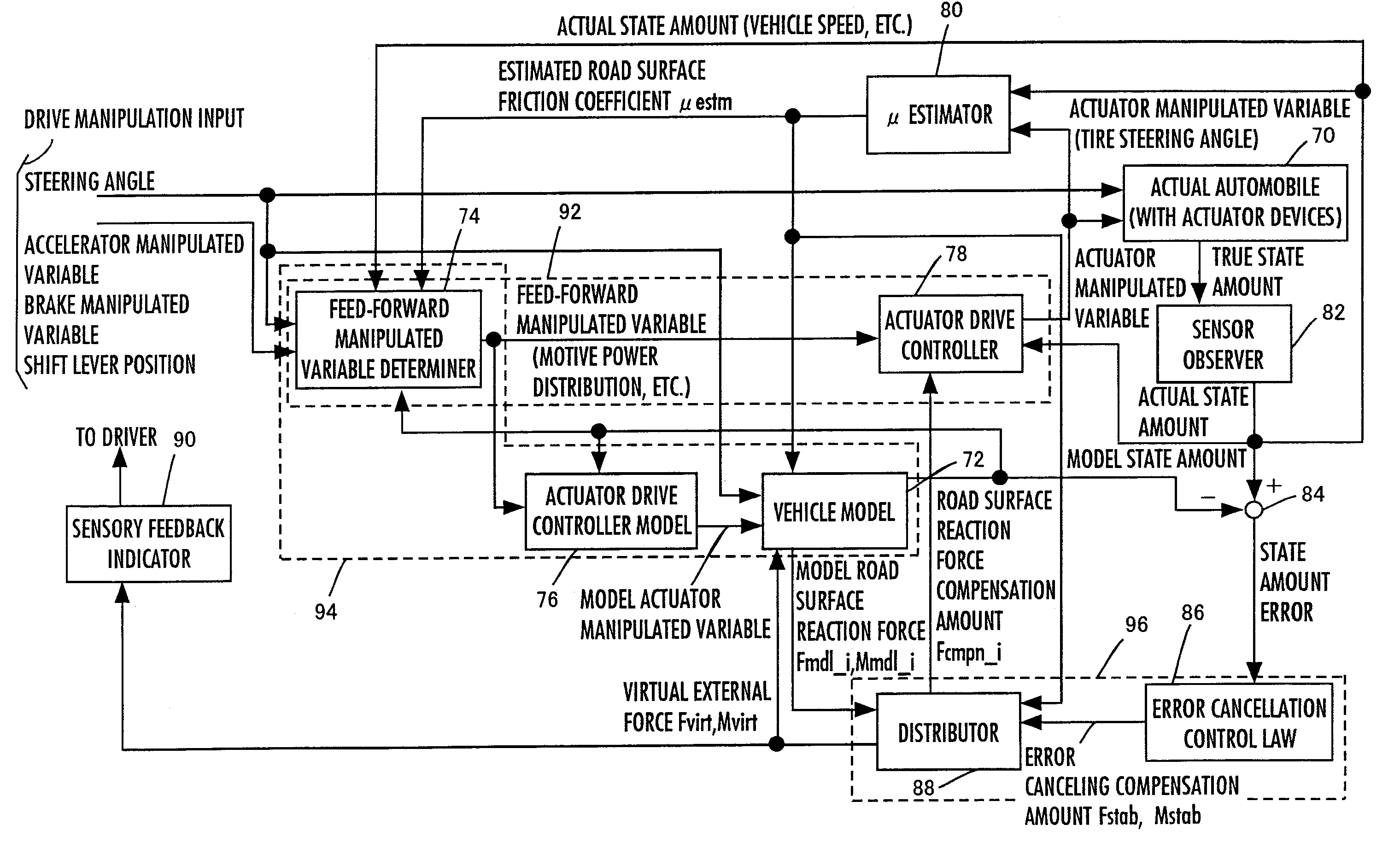
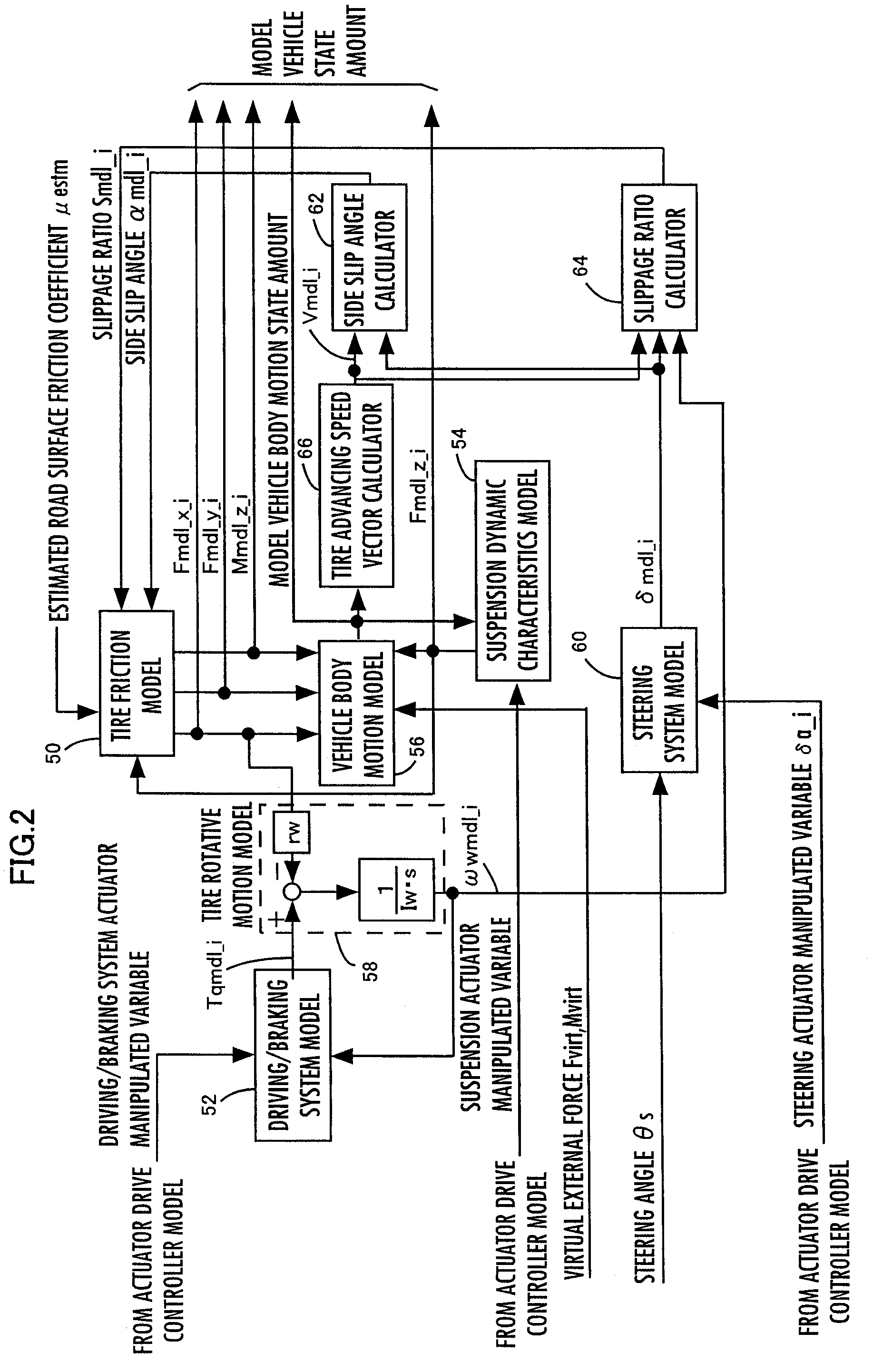
[0078]First, a vehicle model used in arithmetic processing (control processing) of the controller 10 in a first embodiment of the present invention will be explained with reference to FIG. 2 and FIG. 3. FIG. 2 is a block diagram showing a functional construction of a vehicle model 72 of the present embodiment, and FIG. 3 is a flowchart showing the processing of the vehicle model 72.

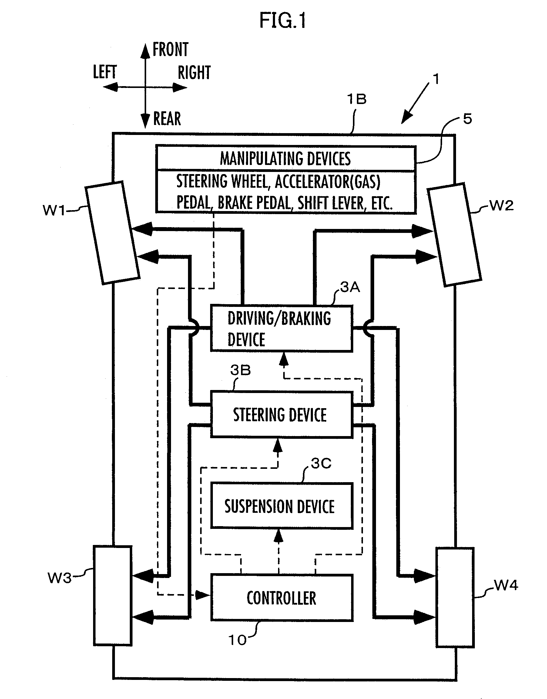
[0079]In the following explanation, subscripts i (i=1, 2, 3, 4) that are the same numbers of wheels W1 to W4 will be attached to variables corresponding to the wheels W1 to W4. The wheels W1 to W4 denote the front left wheel, the front right wheel, the rear left wheel, and the rear right wheel, respectively, of the vehicle 1, as shown in FIG. 1 mentioned above. In the following explanation, the tire provided on the outer periphery (a portion to be in direct contact with a road surface and subjected to a frictional force) of each wheel Wi will be regarded as identical to the wheel, and the wheel Wi will be...

second embodiment

[0178]A second embodiment of the controller for a vehicle in accordance with the present invention will now be explained. The second embodiment differs from the first embodiment only in a part of the construction of the vehicle 1 and a part of control processing of the controller 10; hence, for the same configuration part or the same function part as that of the first embodiment, the same reference numerals as those in the first embodiment will be used and detailed explanation thereof will be omitted.

[0179]The second embodiment uses a vehicle model that is simpler than that in the first embodiment, and controls only an active steering device 3B among actuator devices 3 of a vehicle 1 to bring a state amount difference between the vehicle model and the actual vehicle 1 close to zero.

[0180]In this case, in the present embodiment, the active steering device 3B allows only the steering control angles of front wheels W1 and W2 to be actively manipulated through the intermediary of an act...

third embodiment

[0214]A third embodiment of the present invention will now be explained with reference to FIG. 8 to FIG. 14. FIG. 8 is a block diagram showing a functional construction of a controller for a vehicle according to the third embodiment. As shown in FIG. 8, the third embodiment is provided with a scenario preparer 98 in place of the feed-forward manipulated variable determiner 74 in the first embodiment. Further, a sensory feedback indicator 90 receives outputs from a distributor 88, and information is transmitted from the scenario preparer 98 to the sensory feedback indicator 90. The rest of the construction is the same as that of the first embodiment.

[0215]The following explains an overview of the scenario preparer 98. The scenario preparer 98 generates a time series of the reference state amounts of future motions of a vehicle 1 expected to be desired by a driver after the present time on the basis of a time series of drive manipulation inputs (steering angles, accelerator manipulate...


PUM


Abstract

A control device for a vehicle is equipped with a vehicle model motion determining device for determining a motion of a vehicle (a vehicle model motion) on a vehicle model expressing the dynamic characteristics of a vehicle on the basis of drive manipulated variables, such as an angle of steering by a driver, and a state amount error reaction control device for determining control inputs to an actuator control device of the actual vehicle and the vehicle model motion determining device according to a feedback law on the basis of a difference between a state amount of a vehicle model motion (model state amounts, such as a position or a posture of a vehicle) and a state amount of a motion of the actual vehicle 1 (a state amount error). Based on a state amount error, not only a motion of an actual vehicle but also a vehicle model motion is manipulated, thereby enhancing robustness against disturbance factors or their changes while conducting actuator operation control that is suited to a behavior of the actual vehicle as much as possible.

Description

TECHNICAL FIELD[0001]The present invention relates to a control device for a vehicle having a plurality of wheels, such as an automobile (engine automobile), a hybrid car, an electric car, and a motorcycle.BACKGROUND ART[0002]A vehicle, such as an automobile, is provided with systems, including a driving / braking system that transmits a driving force from a propulsive force generating source, such as an engine, to a wheel or imparts a braking force, a steering system (steering control system) for controlling steering control wheels of a vehicle, and a suspension system that elastically supports a vehicle body on wheels, as main mechanisms. Furthermore, in recent years, there has been known a vehicle provided with a variety of electric or hydraulic actuators to actively (positively) control the operations of the actuators according to a traveling condition or an environmental condition or the like rather than only passively operating the aforesaid systems in response to operations (ma...

Claims


Application Information

Patent Timeline
Patent Type & Authority Patents(United States)
IPC IPC(8): A01B69/00B60G17/015B60T8/58B60W10/04B60W10/06B60W10/08B60W10/10B60W10/18B60W10/188B60W10/20B60W10/22B60W30/00B60W30/02B60W30/045B60W40/02B60W40/06B60W40/072B60W40/076B60W50/00B60W50/06B62D6/00B62D6/02B62D101/00B62D103/00B62D111/00B62D113/00B62D125/00B62D127/00B62D137/00F02D29/02F02D45/00F16F9/50F16F15/02F16H61/02F16H63/50
CPCB60G17/0195B60T8/1755B60W10/20B62D6/008B60W40/10B62D6/003B60W40/068B60W40/064B60W2050/0028B60W10/22
Inventor TAKENAKA, TORU
Owner HONDA MOTOR CO LTD
Why Eureka
Try Eureka