Pressure barrier apparatus

a technology of pressure barrier and apparatus, which is applied in the direction of valve details, valve member-seat contact, fluid removal, etc., can solve the problems of reducing the service life of the barrier member, and reducing the risk of erosion of the barrier member. , to achieve the effect of reducing the risk of erosion of the barrier member

Inactive Publication Date: 2010-04-27
OMEGA COMPLETION TECH
View PDF8 Cites 74 Cited by
  • Summary
  • Abstract
  • Description
  • Claims
  • Application Information

AI Technical Summary

Benefits of technology

[0027]This provides the advantage of minimising the risk of er

Problems solved by technology

One problem associated with operating at high deviations, or at 90 degrees to the vertical, is the absence of gravity to assist the process of lowering tools and instruments into the well.
Additionally, such devices remove the requirement for well intervention in normal wells, thus saving time and cost.
However, this tool is also prone to failure through insufficient dissolution of the salt plug by the fresh water stored in the tool.
In addition, all of the above devices suffer from the disadvantage that failure of operation requires intervention into the well to remedy the problem, which is usually expensive, as a rig is us

Method used


Image

  • Pressure barrier apparatus
  • Pressure barrier apparatus
  • Pressure barrier apparatus

Examples


Embodiment Construction

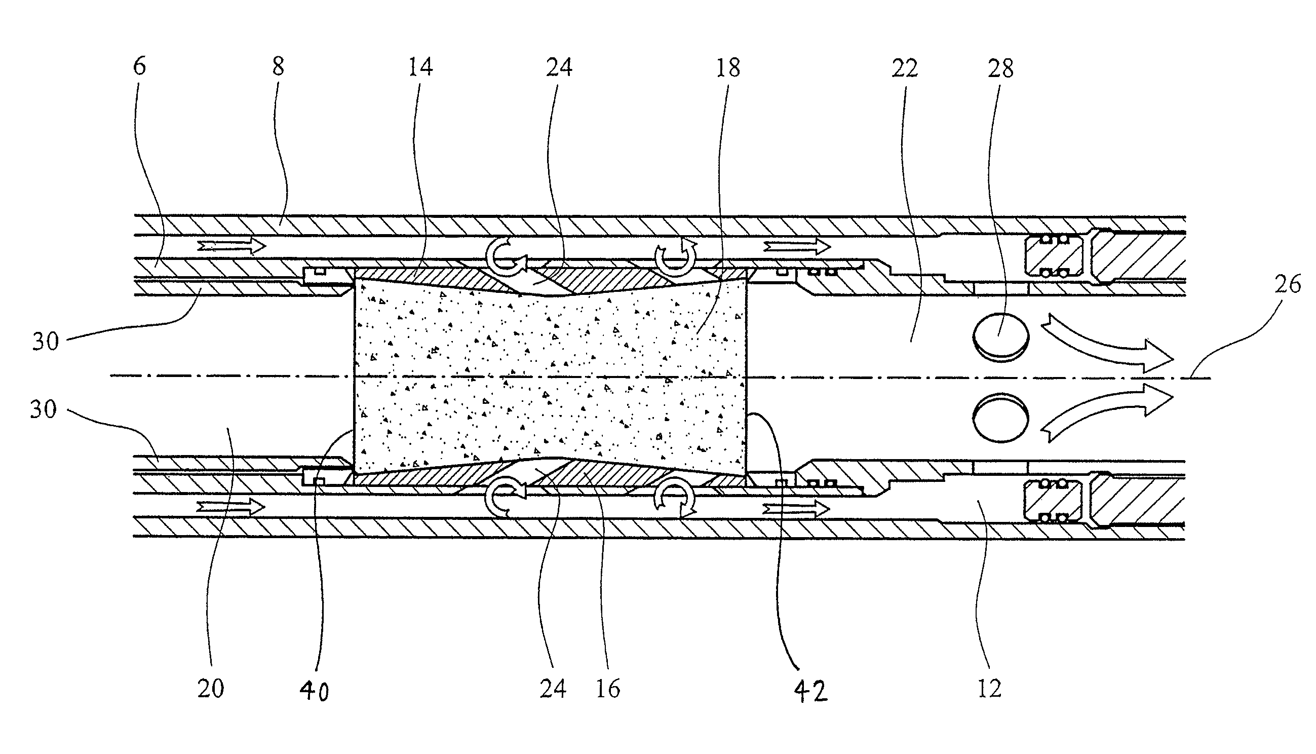
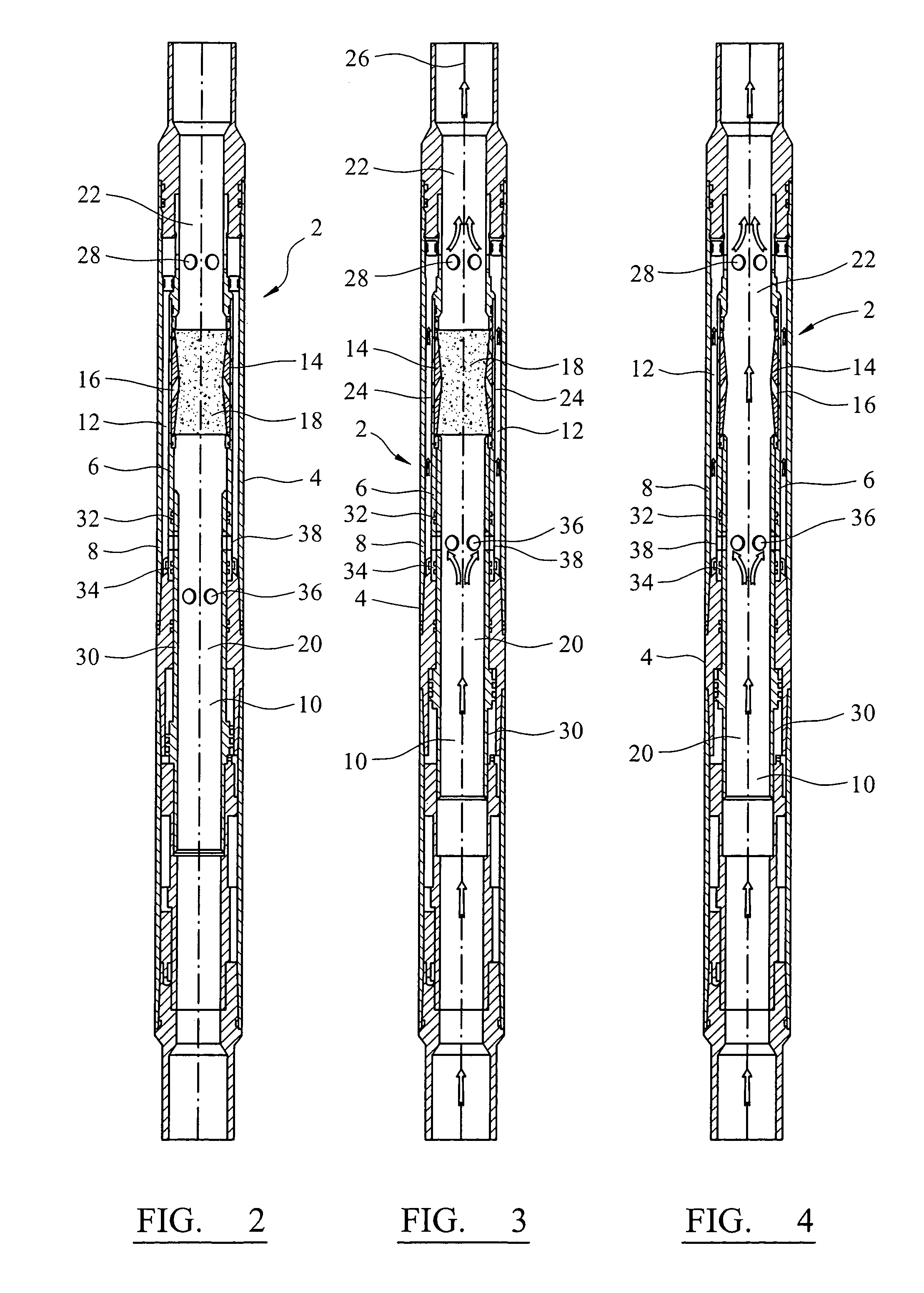
[0037]Referring to FIG. 2, a pressure barrier apparatus 2 embodying the present invention has a housing 4 having screw threads (not shown) at its ends for enabling the apparatus 2 to be incorporated into a downhole tool. The housing 4 includes an inner housing part 6 and an outer housing part 8. The inner housing part 6 defines a first fluid flow passage in the form of a central bore 10 to enable hydrocarbons to be removed from a well (not shown) in an upward direction as shown in FIGS. 2 to 4.

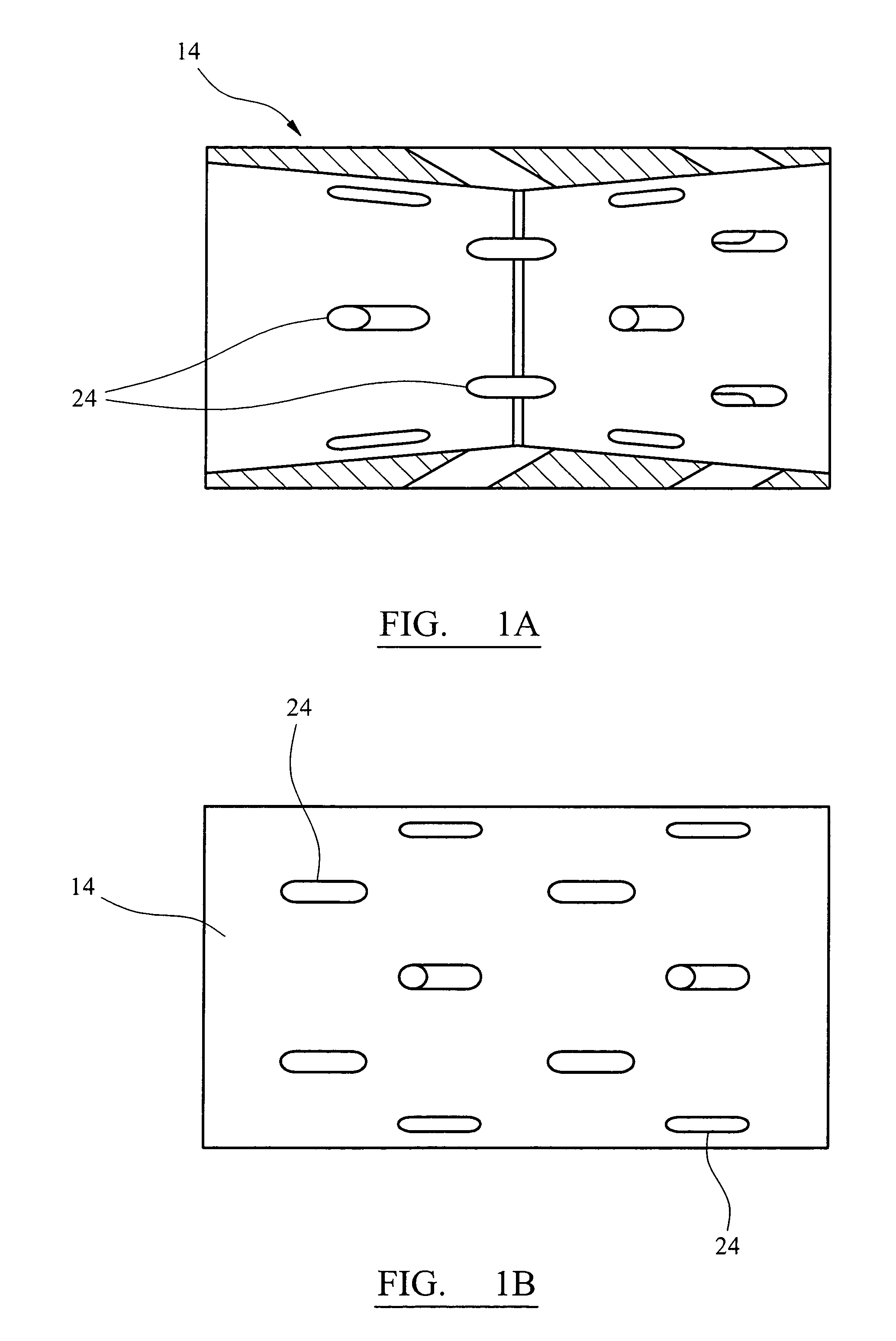
[0038]The inner housing part 6 is located within the outer housing part 8 such that an annular second fluid flow passage 12 is defined between the inner 6 and outer 8 housing parts. A plug housing 14 is located inside the inner housing part 6 and defines a constriction 16 in which an erodeable pressure barrier member 18, formed from sand and a bonding agent, is securely located, such that the central bore 10 is divided into a first part 20 below the pressure barrier member 18 and a second part...


PUM


Abstract

A pressure barrier apparatus 2 for providing a removable pressure barrier in a borehole is described. The apparatus comprises a housing 6, 8 defining a central bore 10 having a first part 20 and a second part 22 separated by an erodeable pressure barrier member 18. The housing also defines a second fluid flow passage 12 for connecting the first part to the second part, and a plurality of conduits 24 for directing fluid onto the barrier member. A sleeve 30 has a first condition in which fluid communication between the first part 20 and the second fluid flow passage 12 is prevented, and a second condition in which fluid is permitted to flow from the first part to the second fluid flow passage to cause erosion of the barrier member.

Description

FIELD OF THE INVENTION[0001]The present invention relates to a pressure barrier apparatus, and relates particularly, but not exclusively, to a pressure barrier apparatus for use in the oil and gas industry.BACKGROUND OF THE INVENTION[0002]In the oil and gas industries, hydrocarbons are obtained from deep in the earth by drilling wells into the ground to access the hydrocarbons. The hydrocarbons are contained in pores in permeable rock which is situated deep in the ground which must be drilled through in order to access the hydrocarbons. Following the drilling phase, the well is clad with a metal casing in order to support the rock and prevent the hole from collapsing. An additional metal tube which is smaller in diameter than the casing, usually of a fixed diameter, provides a conduit to contain the hydrocarbons in a pressure tight environment from near the bottom of the well to the surface.[0003]At the surface, the metal tube (known as tubing) is terminated in a well head which fea...

Claims


Application Information

Patent Timeline
IPC IPC(8): E21B33/00E21B29/00
CPCE21B33/1208E21B34/063
Inventor BUYERS, MARKFORSYTH, DAVID
Owner OMEGA COMPLETION TECH
Why Eureka
Try Eureka