
Serial backplane for medium voltage motor drive system

a motor drive and backplane technology, applied in the field of motor drives, can solve the problems of difficult change of connection between modules in the harness system, relative inflexibility, and fundamental redesign of the circuit board of the system, and achieve the effect of minimizing the number of conductors needed

Inactive Publication Date: 2010-04-27
ROCKWELL AUTOMATION TECH
View PDF4 Cites 9 Cited by
  • Summary
  • Abstract
  • Description
  • Claims
  • Application Information

AI Technical Summary

Benefits of technology

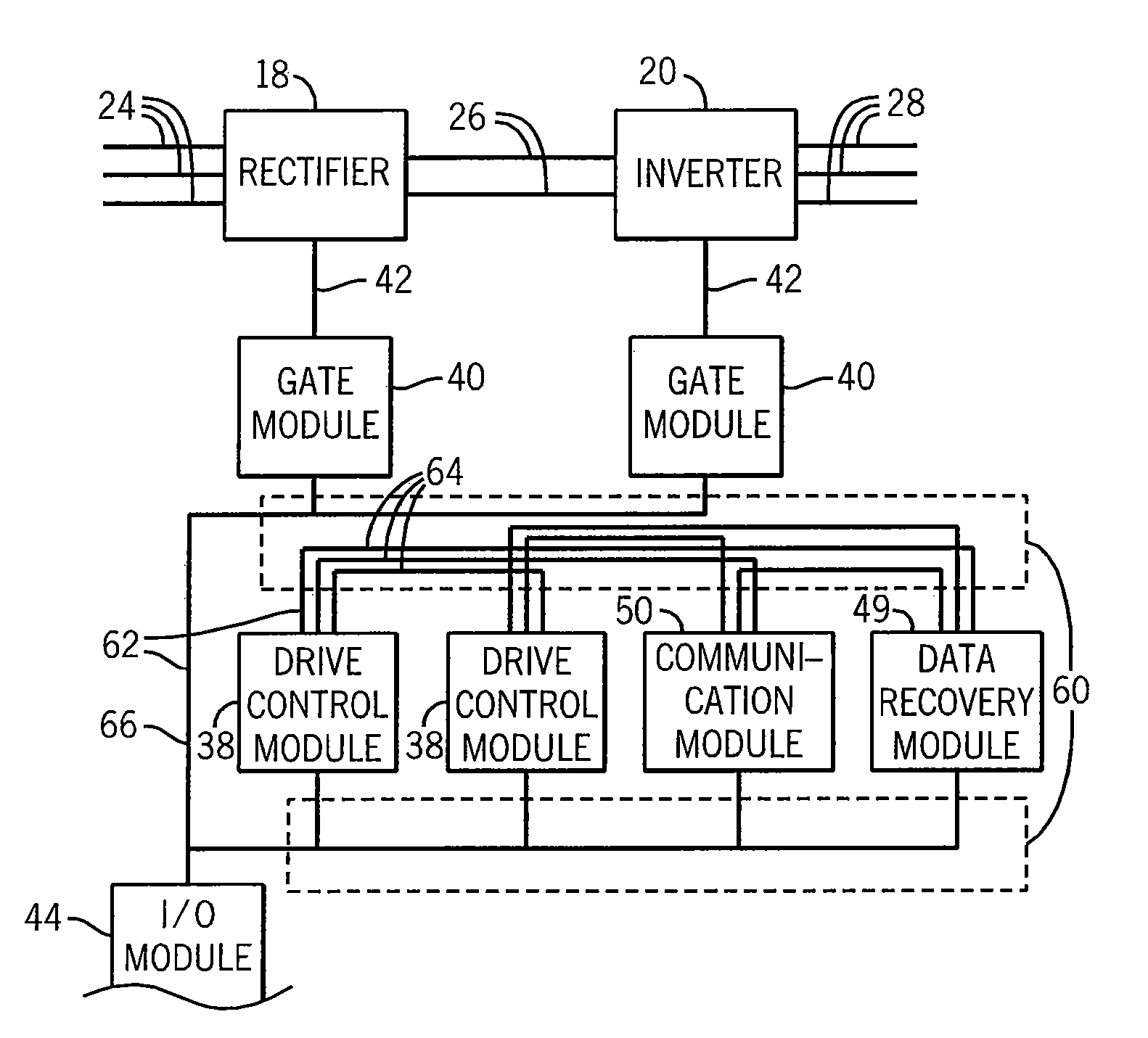
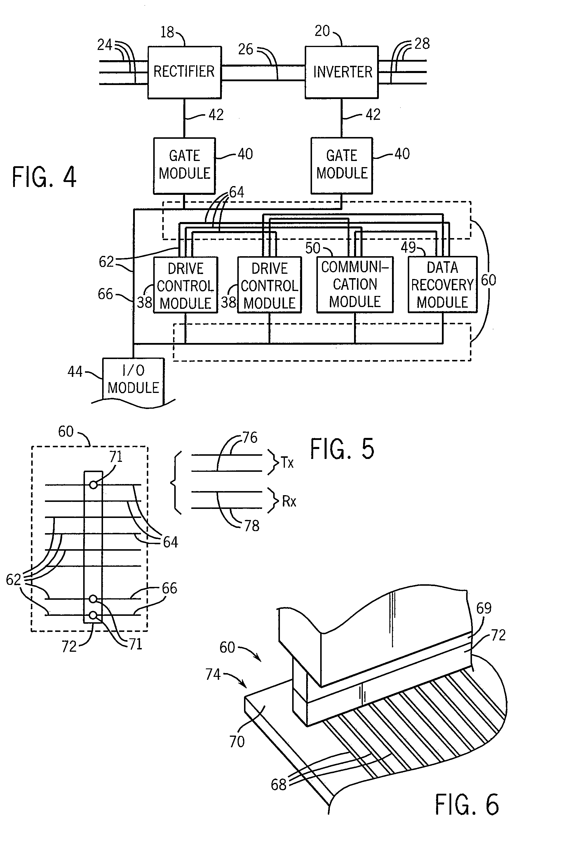
[0008]The present invention combines the benefits of the physical backplane, allowing simple interconnection of modules, with the features of a high-speed serial network minimizing the number of conductors needed to transmit information. This is done by assembling a backplane not out of multiple parallel conductors but rather out of multiple parallel serial communication channels.
[0009]In the resulting “serial backplane” modules may be: easily assembled (through a conventional rack and connector system), flexibly reconfigured (via the addressing system of the serial protocol), resistant to single channel failures (by the use of multiple independent serial channels), and / or upgraded to control more gate signals without cost or space penalties (because of the natural conductor savings in serial data transmission).

Problems solved by technology

A drawback to such parallel bus structures is that they are relatively inflexible.
This may require a fundamental redesign of the circuit boards of the system or may be impractical for reasons of costs or equipment size limitations.
Making and changing the connections between modules in the harness system is difficult, requiring the physical routing of wires between particular boards.

Method used


Image

  • Serial backplane for medium voltage motor drive system
  • Serial backplane for medium voltage motor drive system
  • Serial backplane for medium voltage motor drive system

Examples


Embodiment Construction

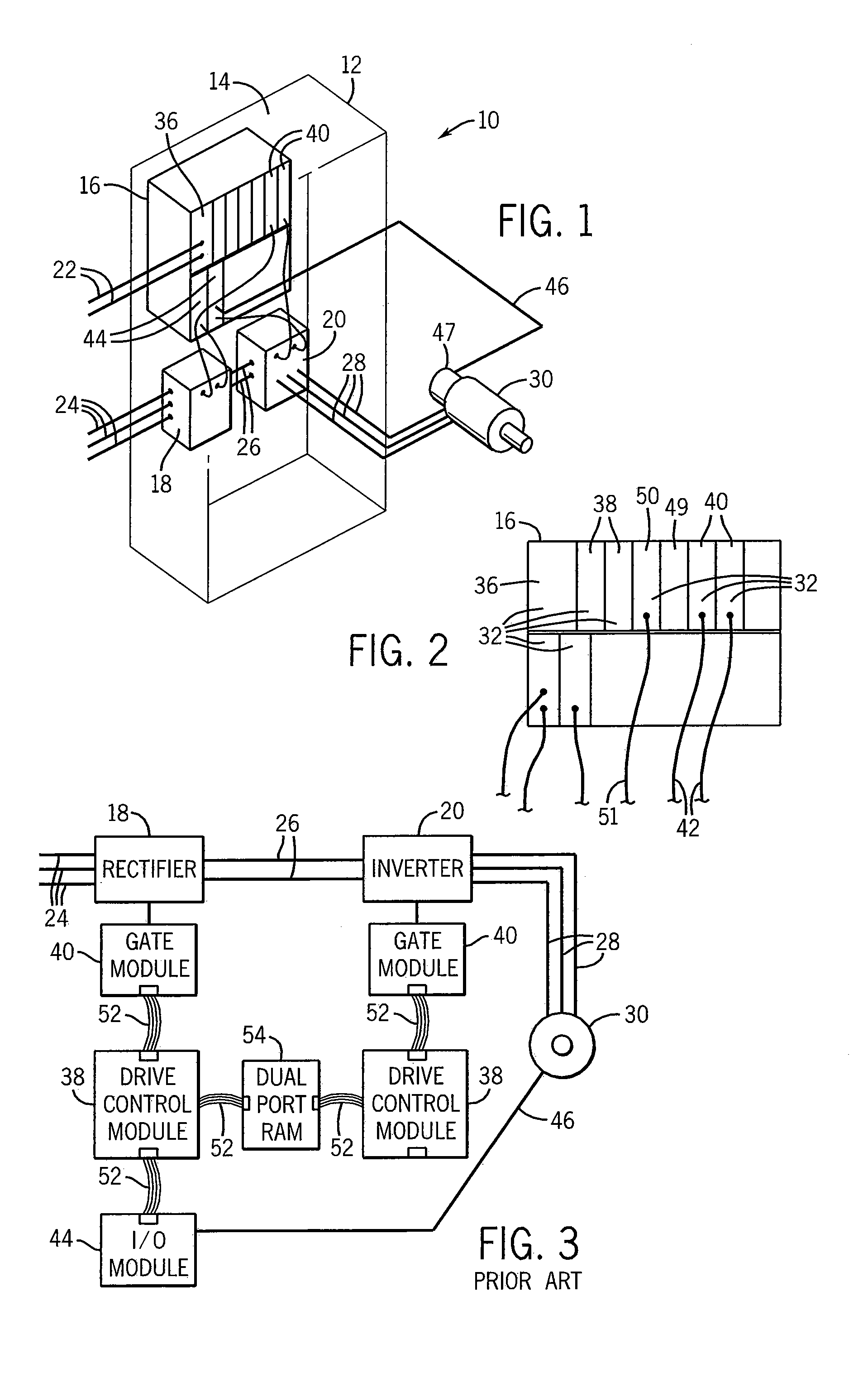
[0043]Referring now to FIG. 1, a motor controller 10 may be assembled within a cabinet 12 limiting access to the motor controller 10. The cabinet 12 may have a back panel 14 supporting a motor drive rack 16, a rectifier 18, and an inverter 20 which together form the principle components of the motor controller 10.

[0044]Within the cabinet 12, the drive rack 16 may receive DC power 22 and the rectifier 18 may receive a source of three-phase power 24 which is converted to DC power 26 and provided to the inverter 20. The inverter 20 may in turn provide for synthesized power waveforms 28 which are transmitted out of the cabinet 12 and connected to the windings of the motor 30.

[0045]Referring now to FIGS. 1 and 2, the motor drive rack 16 may hold a set of modules 32 including a DC-to-DC converter module 36 converting the DC power 22 to convenient voltages for powering the other modules 32. The set of modules 32 may also include one or more drive control modules 38 which, in response to pr...


PUM


Abstract

A hybrid backplane uses multiple, parallel serial communication channels to provide flexibility and robustness in a motor drive control requiring high-speed data communication for the real-time control of motor waveforms.

Description

CROSS-REFERENCE TO RELATED APPLICATIONS[0001]Not Applicable.STATEMENT REGARDING FEDERALLY SPONSORED RESEARCH OR DEVELOPMENT[0002]Not Applicable.BACKGROUND OF THE INVENTION[0003]The present invention relates to motor drives providing synthesized power waveforms to electric motors to control the operation of the motors, and in particular to an improved, modular interconnection system for such motor drives.[0004]Industrial controllers use specialized computers and other electronic circuitry to control industrial processes and machines. The elements of an industrial controller must be easily reconfigured so that the industrial controller may be easily adapted to a variety of applications. For this reason, the elements of an industrial controller are normally modular, allowing different modules to be selected and assembled within a rack that provides for an interconnection between the modules. This approach allows a wide variety of different hardware configurations to be created rapidly....

Claims


Application Information

Patent Timeline
Patent Type & Authority Patents(United States)
IPC IPC(8): G05B11/32
CPCH02M7/003H05K7/1457H05K7/1432H05K7/14325
Inventor WORRALL, STEPHEN
Owner ROCKWELL AUTOMATION TECH
Learn More