Method and device for measurement of electrical bioimpedance

a technology of electrical bioimpedance and measurement method, which is applied in the field of measuring electrical bioimpedance, can solve the problems of relative measurement error of 1/9 or 11 percent, phase error of application of non sine wave signals, and relative error in the range of 10 percent, so as to improve the accuracy of measuring electrical impedance, improve the accuracy of measurement, and reduce the energy consumption of the measuring device

Inactive Publication Date: 2010-04-27
TALLINN UNIVERSITY OF TECHNOLOGY
View PDF10 Cites 35 Cited by
  • Summary
  • Abstract
  • Description
  • Claims
  • Application Information

AI Technical Summary

Benefits of technology

[0017]The purpose of the invention is to increase the accuracy of measurements of the electrical impedance and / or immittance, using the switch-mode generation and demodulation of signals in the case of both analogue and digital signal processing, retaining at the same time the characteristic simplicity of the measurement method, as well as the simplicity and low energy consumption of the measuring device. The undesirable effects caused by both the higher odd harmonics contained in the rectangular wave signals and by the sensitivity of traditional synchronous detectors to odd higher harmonics are essentially suppressed, minimized, or in some embodiments, eliminated.
[0026]A device for implementing of the above method for increasing the accuracy of bio-impedance measurements contains additional functional blocks, the task of which is to shorten the duration of the constant value sections of both the excitation and the reference pulse signals by predetermined time intervals proportional to the signals periods, whereby these predetermined time intervals for the excitation signal and the reference signal have different duration.

Problems solved by technology

For example, the measurement error caused only by the 3rd harmonic of the rectangular signal having the level of ⅓ of the fundamental, can cause a relative measurement error of 1 / 9 or 11 percent.
In addition to the amplitude errors also the phase errors appear from application of the non sine wave signals.
Therefore, the phase error of only some degrees results in a relative error in the range of 10 percent.

Method used


Image

  • Method and device for measurement of electrical bioimpedance
  • Method and device for measurement of electrical bioimpedance
  • Method and device for measurement of electrical bioimpedance

Examples


Embodiment Construction

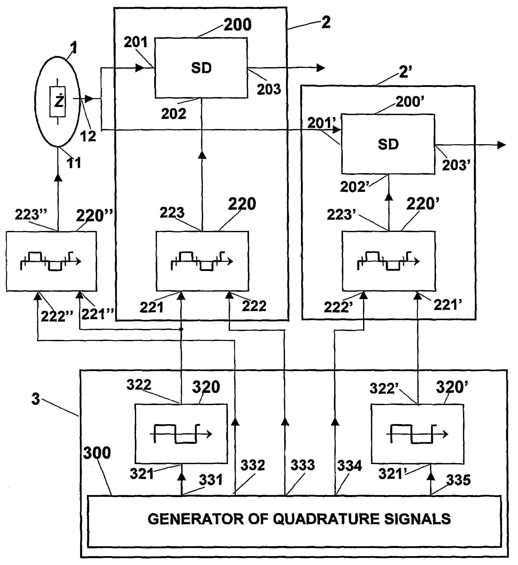
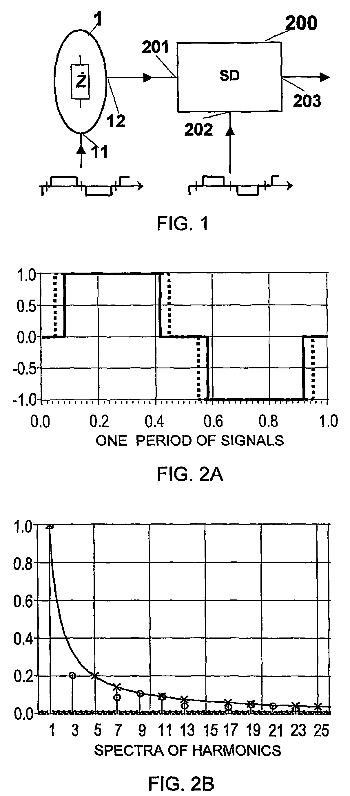
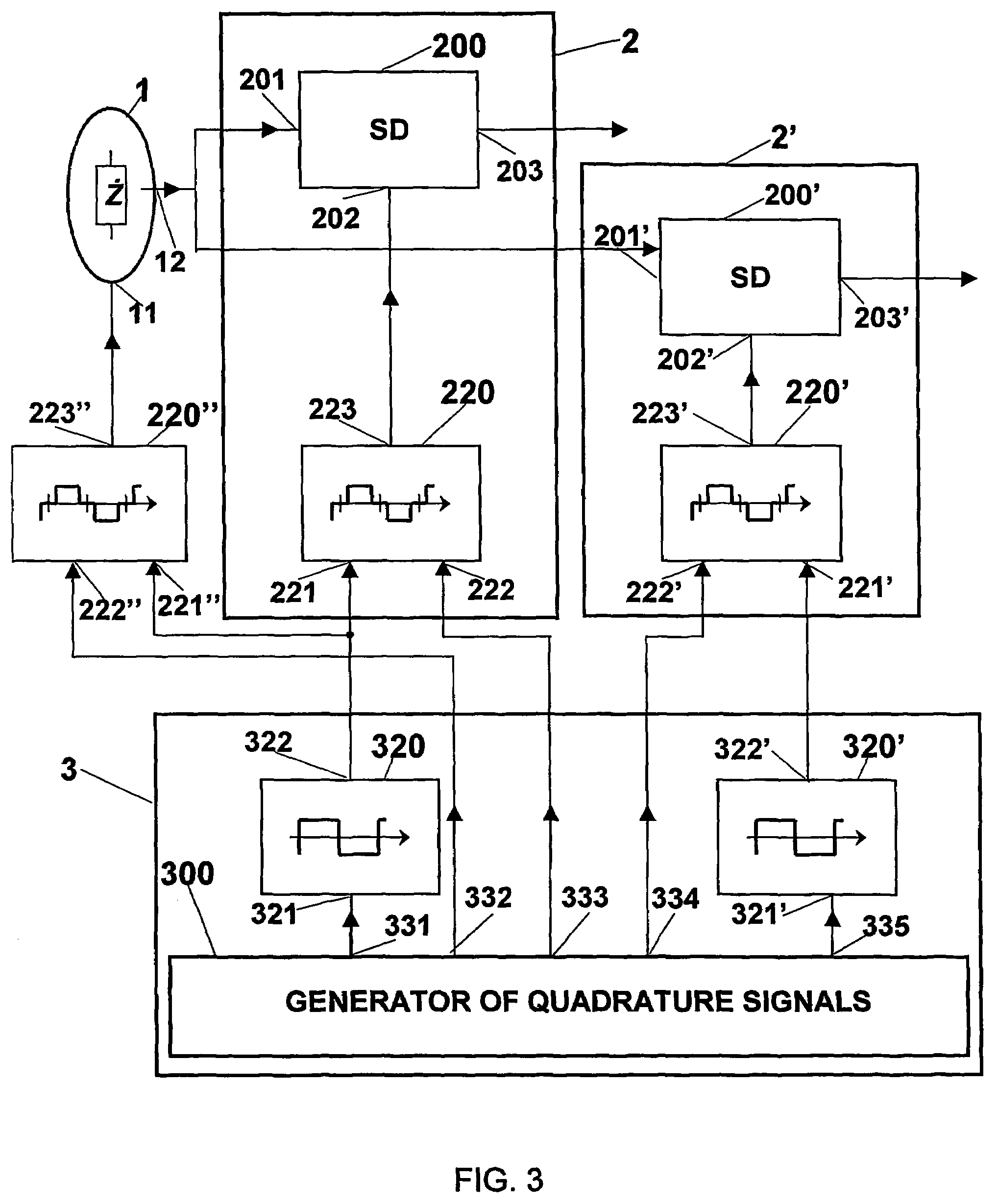
[0037]FIG. 1 presents the method for measurement of the electrical impedance of bio-object is described. A symmetrical bipolar pulse-form periodical excitation signal (electrical current or voltage) is applied to the input 11 of the bio-object 1, a corresponding reaction of the bio-object to the mentioned excitation signal is measured from the output 12, which is connected to the input 201 of the synchronous detector 200. A symmetrical bipolar pulse-form periodical signal is also applied to the reference input 202 of the synchronous detector 200, but it has different spectral content in comparison with the excitation signal applied to the input 11 of the bio-object 1.

[0038]Multiplication of pulse-form signals causes misleading measurement errors and uncertainty of results because of their higher harmonics content. Therefore, a former of shortened pulse 220 (FIG. 7) is used in the proposed solution, the task of which is to shorten the bipolar rectangular signal so that by introducing...


PUM


Abstract

A method of measuring of an electrical bio-impedance, the method being characterized in that a symmetrical bipolar pulse-form periodical excitation signal (electrical current or voltage) is applied to the input (11) of the bio-object (1), a corresponding reaction of the bio-object to the mentioned excitation signal is measured from the output (12), which is connected to the input (201) of the synchronous detector (200). A symmetrical bipolar pulse-form periodical signal is also applied to the reference input (202) of the synchronous detector (200), whereby both pulse-form signals are shortened by the predetermined time interval in each half period of the signal, said time intervals being different for the excitation and reference signals. The proposed method ensures an increased accuracy of the impedance analysis by decreasing the influence of the higher harmonics in the spectra of the excitation and reference signals of the synchronous detectors to the measurement result. The use of the rectangular signals ensures that the device for implementing of the proposed method has a simple design and low power consumption.

Description

RELATED APPLICATIONS[0001]This application is a national phase application of PCT Application Serial NumberPCT / EE2003 / 000006 filed Nov. 28, 2003, which, in turn, claims priority to Estonian Application No. P200200677, filed Dec. 6, 2002. Each of these applications is herein incorporated in its entirety by reference.TECHNICAL FIELD[0002]The invention is related to the measurement of electrical impedance, particularly to measurement of the electrical bio-impedance, and is based on the synchronous signal conversion or lock-in techniques used for converting of measuring signals for forming the measuring (excitation) signal as well as for demodulating the response signal from the object.[0003]The main field of application of the invention is related to the measurement of impedance in portable and / or implantable medical means and apparatuses, which are used with the aim to get diagnostic results and to determine the conditions of implanted and / or implantable and transplantable organs and ...

Claims


Application Information

Patent Timeline
Patent Type & Authority Patents(United States)
IPC IPC(8): A61B5/05A61B5/053
CPCA61B5/053
Inventor MIN, MARTKINK, ANDRESLAND, RAULPARVE, TOOMAS
Owner TALLINN UNIVERSITY OF TECHNOLOGY
Why Eureka
Try Eureka