Celestial navigation system for an autonomous robot

a navigation system and autonomous robot technology, applied in the field of robotic systems, can solve the problems of limited ability, time-consuming, or dangerous, types of systems, useful for obstacle avoidance, and systems, however, are also limited in their ability to allow a robot to navigate effectively

Active Publication Date: 2010-04-27
IROBOT CORP
View PDF479 Cites 397 Cited by
  • Summary
  • Abstract
  • Description
  • Claims
  • Application Information

AI Technical Summary

Benefits of technology

[0008]In one aspect, the invention relates to a navigational system for an autonomous robot that includes a stationary transmitter for emitting at least two signals, the signals directed toward a surface remote from a working area, such as a wall bordering a floor (upon which a robot operates), or a ceiling located above the floor. The system also includes a receiver mounted to an autonomous robot containing various power, motive, and task-related components. The receiver detects the two signals emitted by the emitter, and a processor determines the location of the robot within the working area based upon the received signals. Generally, the signals directed to the remote surface are infrared signals, but other embodiments are also possible. The robot detects the signal energy reflected from the ceiling and, by calculating the azimuth and elevation of the signals relative to the robot, can determine its location.

Problems solved by technology

Automated robots and robotic devices are becoming more prevalent today and are used to perform tasks traditionally considered mundane, time-consuming, or dangerous.
These types of systems, which are useful for obstacle avoidance, are limited in their ability to allow a robot to track its location within a room or other working environment.
These systems, however, are also limited in their ability to allow a robot to navigate effectively in a complex environment, as they allow the robot to only recognize when objects are in its immediate vicinity.
These limitations of the above types of navigational systems are, at present, a hurdle to creating a highly independent autonomous robot, which can navigate in a complex environment.

Method used


Image

  • Celestial navigation system for an autonomous robot
  • Celestial navigation system for an autonomous robot
  • Celestial navigation system for an autonomous robot

Examples


Embodiment Construction

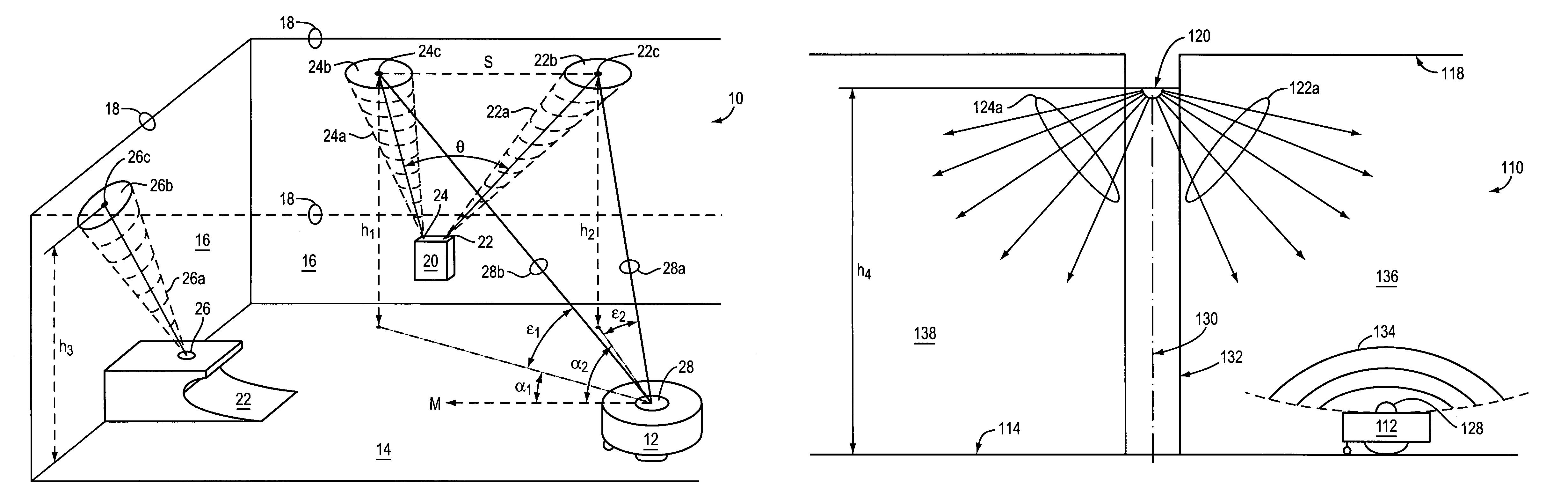
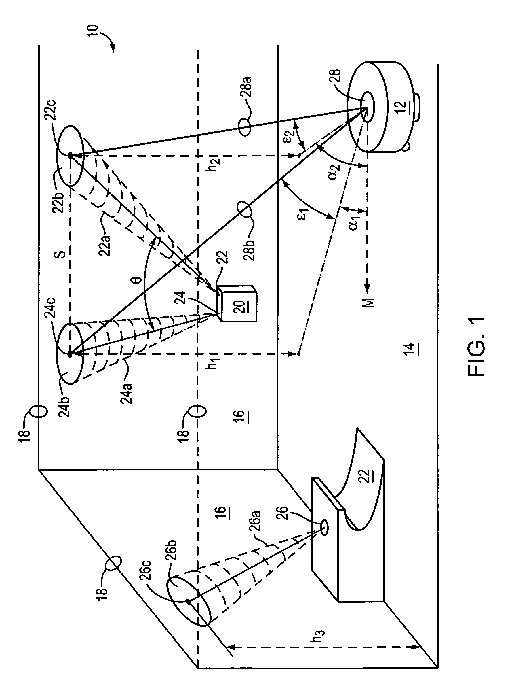
[0029]FIG. 1 is a schematic view of a navigational system 10 for an autonomous robot 12 in accordance with one embodiment of the invention. The components of the system 10 include, in this embodiment, a transmitter 20, a charging or base station 22, and a robot 12 that operates in a room or other similar working area 14. In this case, the working area 14 is a floor of a room, bounded at least in part by walls 16. Borders of a ceiling 18 also intersect the walls 16 and are remote from the working area 14. The depicted transmitter 20 includes two emitters 22, 24. In this embodiment, the base station 22 may include an emitter 26 as well. In various embodiments, any combination or quantity of emitters may be used on the base station 26, or transmitter 20, or both. The robot 12 includes an on-board microprocessor, power and drive components, task-specific components (dirt sensors, vacuums, brushes, etc.), and at least one receiver, such as a infrared receiver 28. The robot 12 may also in...


PUM


Abstract

A navigational control system for an autonomous robot includes a transmitter subsystem having a stationary emitter for emitting at least one signal. An autonomous robot operating within a working area utilizes a receiving subsystem to detect the emitted signal. The receiver subsystem has a receiver for detecting the emitted signal emitted by the emitter and a processor for determining a relative location of the robot within the working area upon the receiver detecting the signal.

Description

RELATED APPLICATIONS[0001]This application incorporates by reference in its entirety and claims priority to U.S. patent application Ser. No. 60 / 586,046, entitled “Celestial Navigation System for an Autonomous Robot,” filed on Jul. 7, 2004.TECHNICAL FIELD[0002]The present invention relates generally to robotic systems and, more specifically, to navigational systems for autonomous robots.BACKGROUND[0003]Automated robots and robotic devices are becoming more prevalent today and are used to perform tasks traditionally considered mundane, time-consuming, or dangerous. As the programming technology increases, so too does the demand for robotic devices that can navigate around a complex environment or working space with little or no assistance from a human operator.[0004]Robotic devices and associated controls, navigational systems, and other related systems are being developed. For example, U.S. Pat. No. 6,594,844 discloses a Robot Obstacle Detection System, the disclosure of which is her...

Claims


Application Information

Patent Timeline
Patent Type & Authority Patents(United States)
IPC IPC(8): G06F19/00
CPCG05D1/0225G05D1/0234G05D1/0227G05D2201/0215G05D1/0274G05D2201/0203G05D1/0238Y10S901/01B60L53/38G05D1/0242Y02T10/70Y02T10/7072Y02T90/12H02J50/001H02J50/12H02J50/20H02J2310/14H02J50/90H02J50/10A47L9/2826A47L9/2836A47L9/2894A47L2201/022A47L2201/04A47L2201/06G01C21/20G01C21/206G01S5/0284G05D1/0016G05D1/0088G05D1/0219G05D1/0276G06F17/00H04W88/06G05D1/0246
Inventor CHIAPPETTA, MARK JOSEPHFRANKEL, JAMES PAUL
Owner IROBOT CORP
Why Eureka
Try Eureka