System for feeding a liquid fluid through a filter

a technology of liquid fluid and filter, which is applied in the direction of filtration separation, water cleaning, separation processes, etc., can solve the problems of high variability in runoff flow rate and large flow rate of treatment devices

Inactive Publication Date: 2010-05-04
ADVANCED DRAINAGE SYST +1
View PDF22 Cites 9 Cited by
  • Summary
  • Abstract
  • Description
  • Claims
  • Application Information

AI Technical Summary

Benefits of technology

[0008]The present invention employs a large vault or tank for receiving the runoff water. There are one or more small tanks in the large tank (vault). Each small tank is inverted and receives water, from the large tank, at its open lower end. The water entering the small tank rises, as the water level in the large tank rises, and flows upward through a filter. When the water level rises above the top of the filter it enters an outlet tube or pipe and then flows downwardly along the center-line of the filter. A float, a valve and a check valve may cause the system to function as a siphon and feed the filtered clean water to an outlet. Alternatively the siphoning effect will occur if the inside diameter of said outlet tube is small enough to form a partial vacuum.

Problems solved by technology

BaySaver is licensed under U.S. patents on several different physical separators, including patents U.S. Pat. Nos. 5,746,911 and 6,264,835, both titled “Apparatus for separating a heavy fluid from a light fluid.” While physical separators accomplish a great deal and are an important factor in environmental protection, they do not remove dissolved contaminants, nor do they remove sediment particles in the fine silt and clay size range.
One of the challenges of stormwater management is dealing with the highly variable runoff flow rates, that result from storms.
In stormwater applications, treatment devices are subjected to widely varying flow rates, from very slow trickles to the runoff resulting from torrential downpours.

Method used


Image

  • System for feeding a liquid fluid through a filter
  • System for feeding a liquid fluid through a filter
  • System for feeding a liquid fluid through a filter

Examples


Embodiment Construction

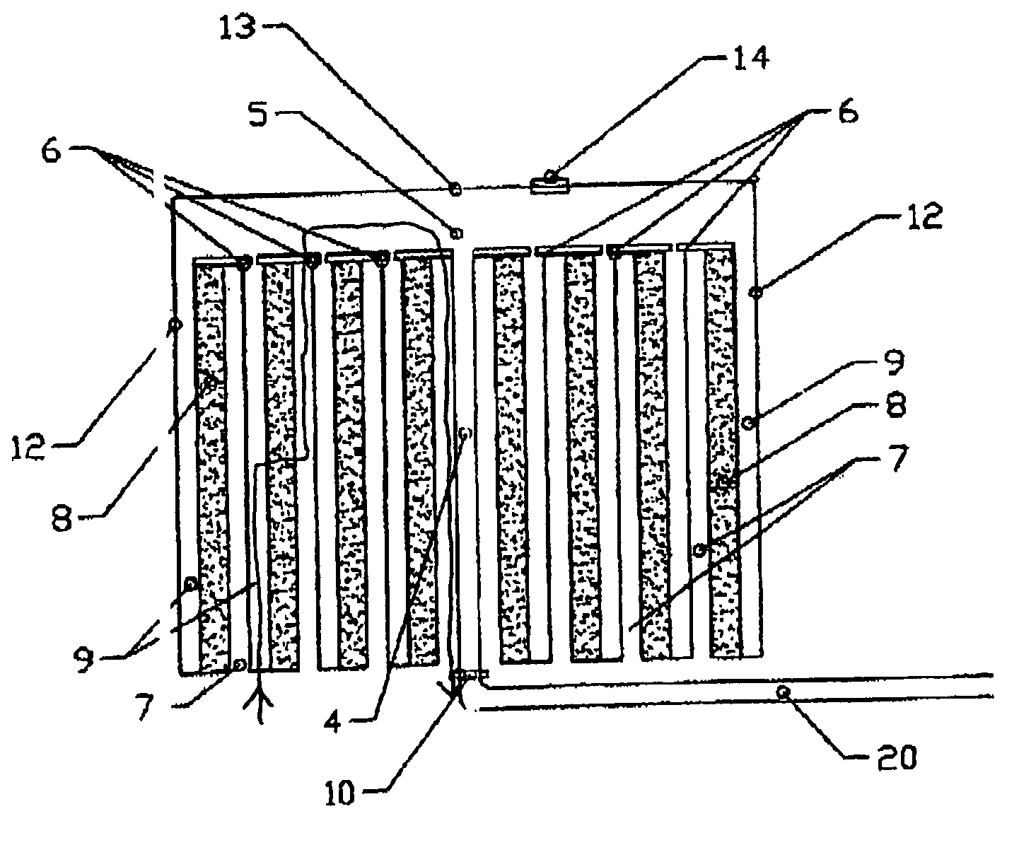
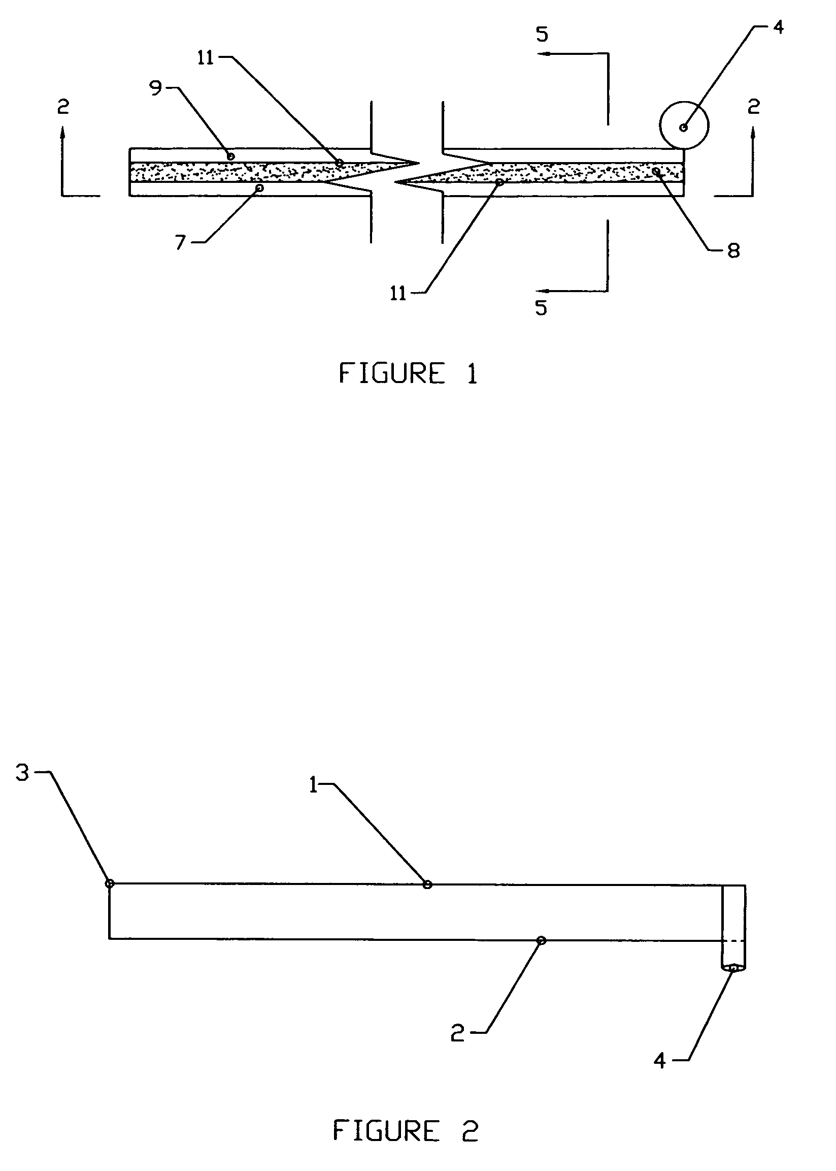
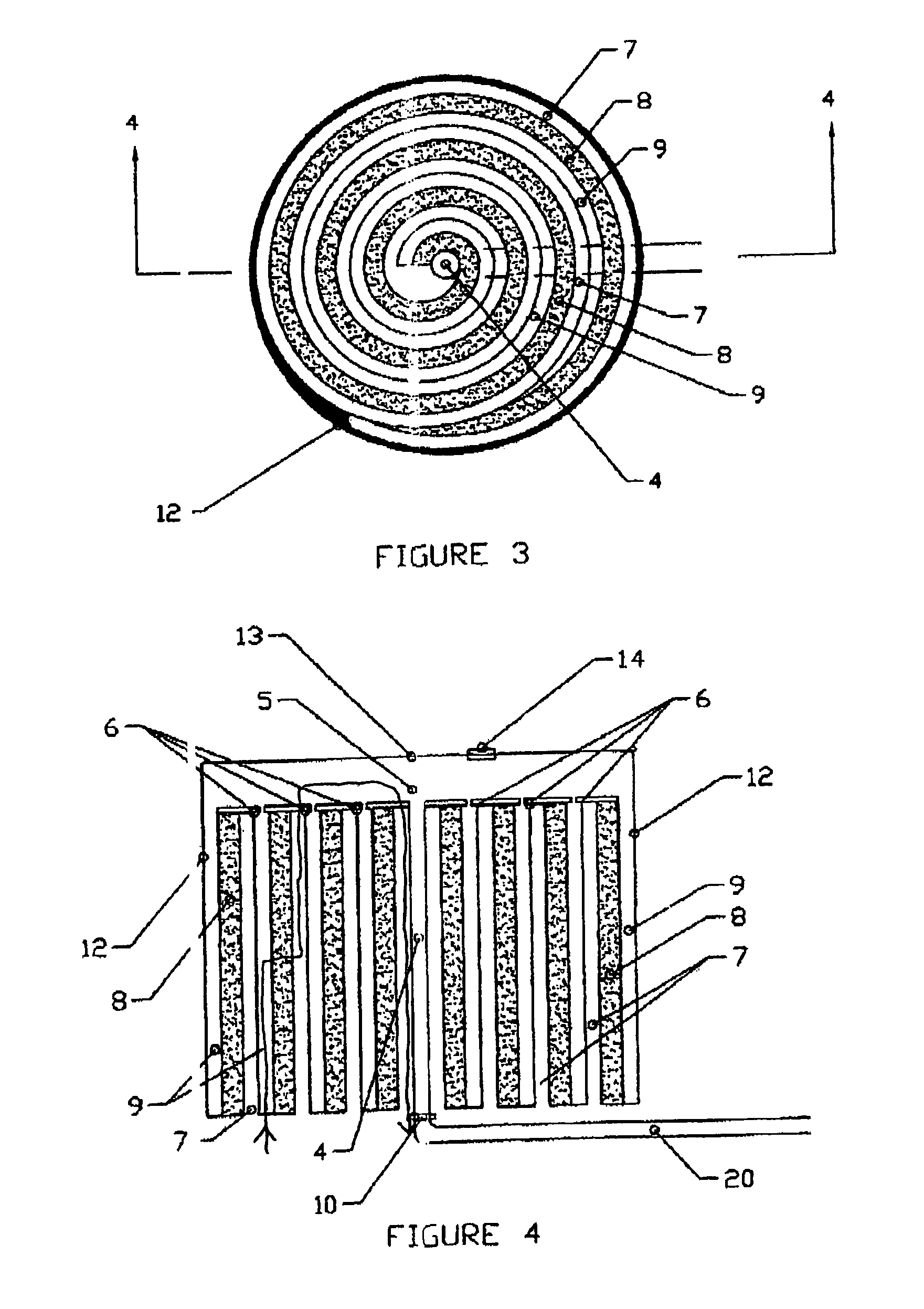
[0021]The invention is a modular filter system for stormwater runoff treatment. The filter itself comprises several layers of drainage material and filter material as described in the copending application of Thomas E. Pank, which has been published, see Publication No. U.S. 2005-0178719A-2 dated Aug. 18, 2005.

[0022]The complete invention comprises a filter cartridge 21 that is placed in a housing, or large tank, 19. Contaminated fluid enters the housing input tank 19 through an inlet means 17 and accumulates within said housing 19. The fluid may be contaminated with solid particles, undesirable gases, dissolved chemicals, or other pollutants. Within the housing 19, the contaminated fluid enters the filter cartridge 21 and is directed through the filter media 11 contained in said cartridge 21 to remove contaminants from said fluid. Said fluid displaces air within said cartridge 21 through a check valve 14, establishing a siphon effect. The siphon continues to pull fluid from said ho...


PUM

PropertyMeasurementUnit
widthaaaaaaaaaa
thicknessaaaaaaaaaa
thickaaaaaaaaaa

Abstract

A large vault or tank receives the runoff water to be cleaned. There are one or more small tanks in the large tank (vault). Each small tank is inverted and receives water at its open lower end, from the large tank. The water entering the small tank rises, as the water level in the large tank rises, and flows upward through a filter. When the water level rises above the top of the filter it enters an outlet tube or pipe and then flows downwardly along the center-line of the filter. A float, a valve and a check valve may cause the system to function as a siphon and feed the filtered clean water to an outlet. Alternatively the siphoning effect will occur if the inside diameter of said outlet tube is small enough to form a partial vacuum.

Description

RELATED CASE[0001]We claim the benefit of our prior U.S. Provisional application Ser. No. 60 / 718,717, filed Sep. 20, 2005. The present application is a continuation-in-part of prior copending application Ser. No. 11 / 030,939 filed Jan. 7, 2005 of co-inventor Thomas E. Pank. We also claim the benefit of co-inventor Pank's provisional 60 / 543,942 filed Feb. 12, 2004.BACKGROUND OF THE INVENTION[0002]This invention was developed by BaySaver Technologies Inc. (BaySaver) a manufacturer of stormwater pollution controls based in Maryland. BaySaver is licensed under U.S. patents on several different physical separators, including patents U.S. Pat. Nos. 5,746,911 and 6,264,835, both titled “Apparatus for separating a heavy fluid from a light fluid.” While physical separators accomplish a great deal and are an important factor in environmental protection, they do not remove dissolved contaminants, nor do they remove sediment particles in the fine silt and clay size range.[0003]Filtration is a pr...

Claims


Application Information

Patent Timeline
Patent Type & Authority Patents(United States)
IPC IPC(8): B01D29/00C02F1/00
CPCB01D25/24B01D25/30B01D2201/206
Inventor PANK, THOMAS E.MEYERMANN, AUSTIN T.
Owner ADVANCED DRAINAGE SYST
Why Eureka
Try Eureka