Signal processing method in a dental radiology apparatus

a dental radiology and signal processing technology, applied in the field of dental radiology, can solve problems such as not being able to do by most users

Active Publication Date: 2010-05-04
CARESTREAM DENTAL TECH TOPCO LTD
View PDF12 Cites 9 Cited by
  • Summary
  • Abstract
  • Description
  • Claims
  • Application Information

AI Technical Summary

Benefits of technology

[0027]According to the report indicating the exposure level used, it thus becomes possible to adapt the exposure level of the x-ray sensor for later analog image output signals.
[0028]Thus the invention makes the dental radiology apparatus used safer for patients than before insofar as any high x-ray doses which patients are subject to can be detected more easily than before.
[0029]Furthermore, the invention enables easier adjustment of the dental radiology apparatus than before, as the user is automatically informed of the exposure level used.
[0034]By ensuring that the amplitude of variation of the analog signal corresponds with a wide enough variation range of the digital data, and thus by adapting the x-ray dose emitted, the amplitude of the digital data is maximized, thus improving the conversion's signal-to-noise ratio by limiting the noise of said digital-analog conversion.
[0043]When the x-ray exposure level is low, the analog signal is low and thus the variation range of the digital data is reduced.
[0051]This additional step avoids any variations in the analog signal amplitude from one sensor to another. The amplitude of analog signal variation ideally corresponds to the variation amplitude of the digital data, called input window of the analog-digital converter. It is desirable through design to ensure that the variation amplitude of the analog signal is not less than the window of the analog-digital converter, in order to take full advantage of the variation ranges of the digital data. Conversely, where the variation amplitude of the analog signal may, for a given sensor, exceed the window of the analog-digital converter, the data indicating an overflow (overflow bit) also supply an indication of saturation of the signal processing chain.

Problems solved by technology

In the dental radiological equipment that has just been described, it is not known whether the x-ray dose used to pass through a patient's tooth is sufficient to produce a good quality image on the display screen (correct exposure level), whether the dose is insufficient (under-exposure) or even excessive (over-exposure).
However, this is not something most users can do, as they do not always know how to analyze the tooth image reliably.

Method used


Image

  • Signal processing method in a dental radiology apparatus
  • Signal processing method in a dental radiology apparatus
  • Signal processing method in a dental radiology apparatus

Examples


Embodiment Construction

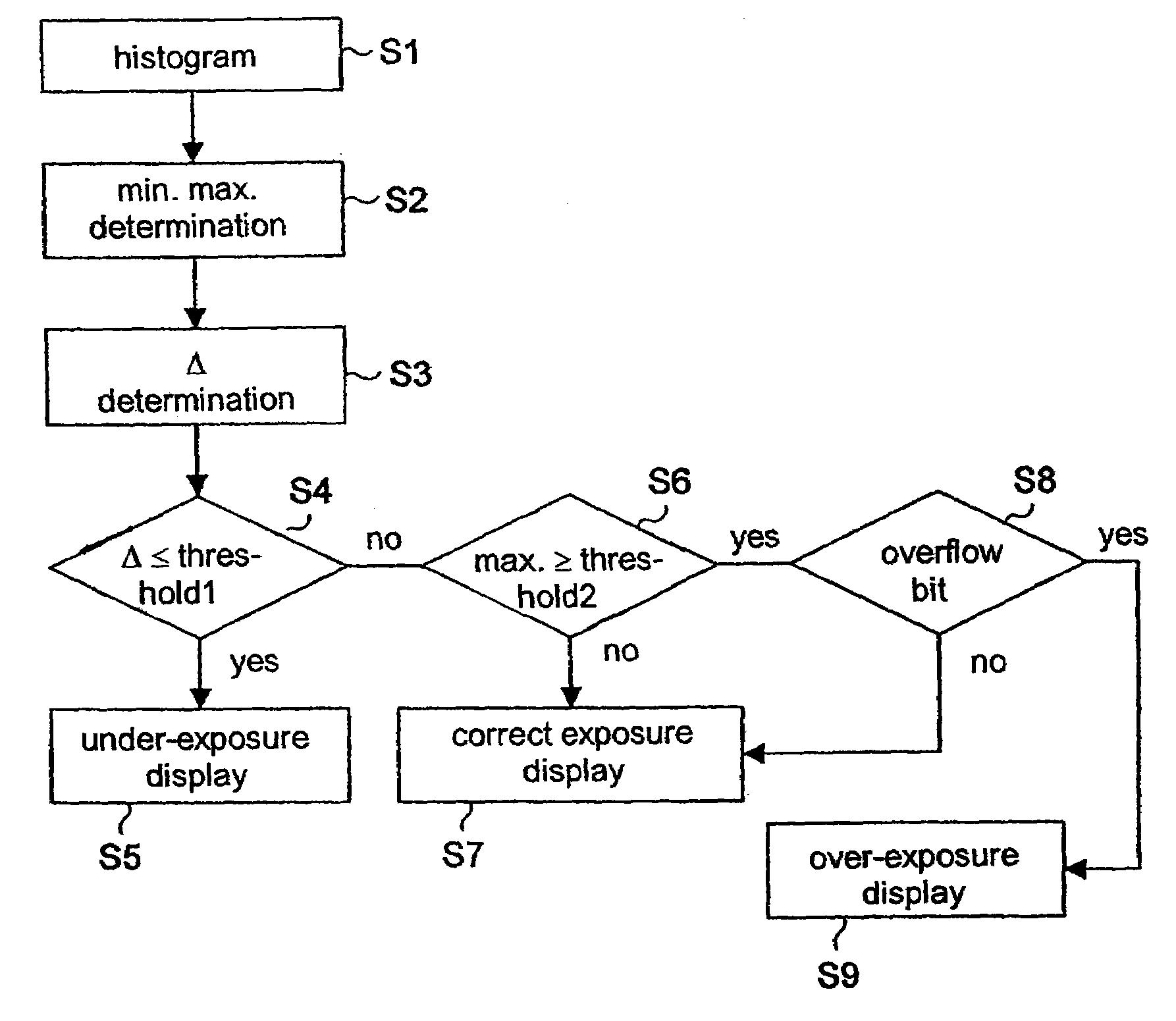
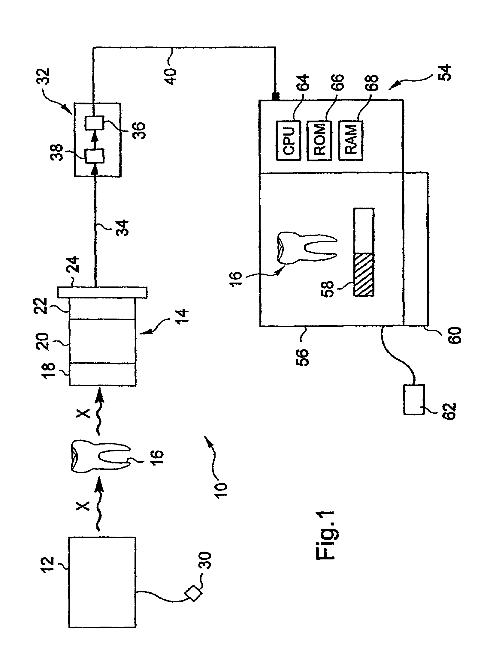
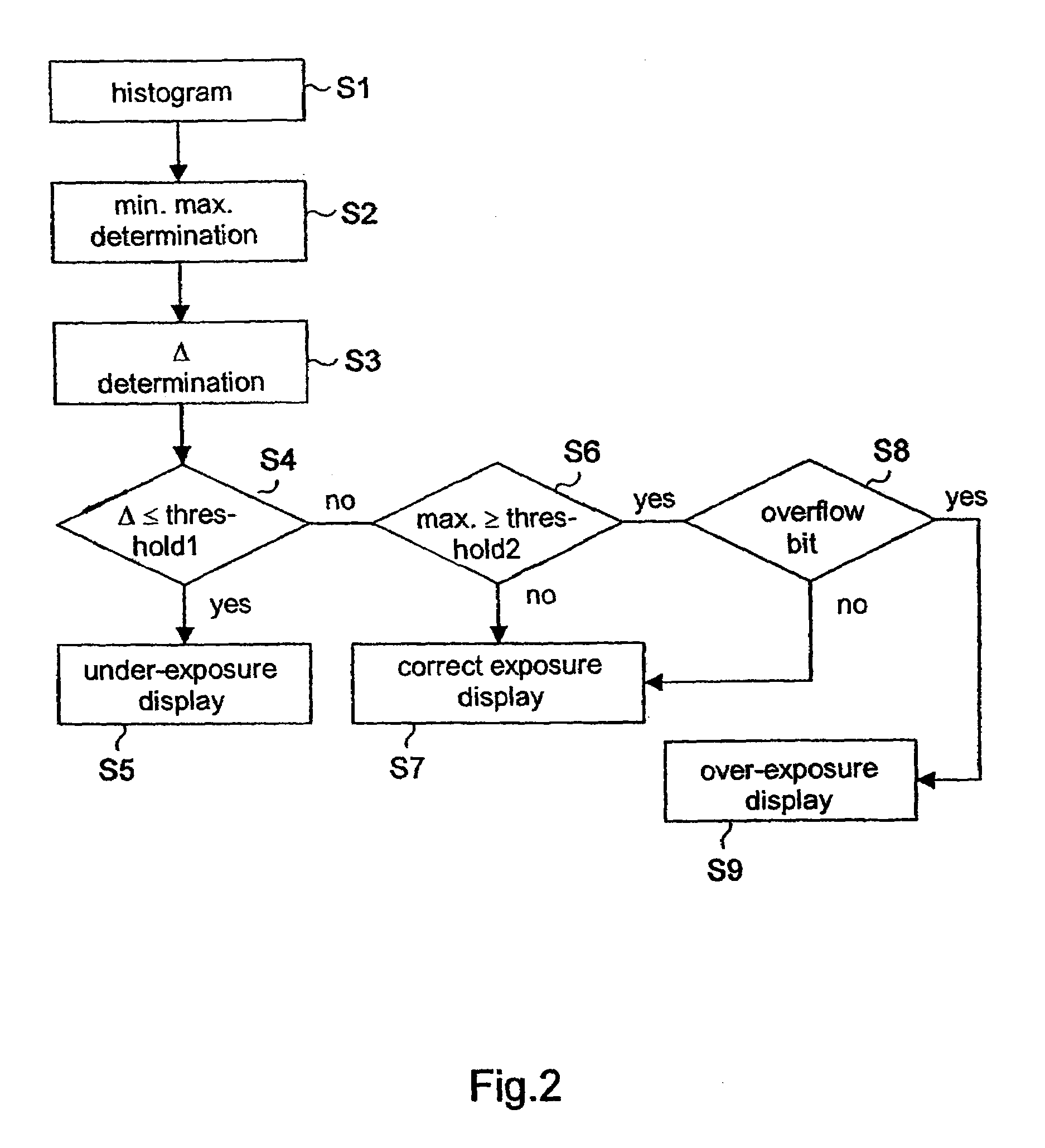
[0066]As represented in FIG. 1, an x-ray dental radiology apparatus 10 comprises an x-ray source 12 placed outside a patient's mouth and an intraoral radiation sensor 14 arranged in a patient's mouth, behind a tooth 16, and which is capable of receiving the x-rays that have passed through the tooth.

[0067]The sensor 14 comprises, in the propagation order of the radiation, a scintillator 18 that converts the x-rays that have passed through the tooth into visible light, possibly a fiber optic plate that, on the one hand, includes metal particles intended to absorb the part of the x-rays received by the scintillator and not converted into visible light and, on the other hand, conducts the visible light thus converted to a detector 22. This detector is mounted on a ceramic substrate 24 and converts the visible radiation from the optical fibers into one or more analog electrical signals.

[0068]It may be noted that other sensor structures can be suitable including, for example, a sensor wit...


PUM


Abstract

The application relates to a signal processing method in a dental radiology apparatus comprising an intraoral sensor that delivers at least one analog image output signal in response to an exposure of said sensor to x-rays, characterized in that it includes the following steps: conversion of said at least one analog image output signal into one digital image output signal, processing of the digital image output signal to obtain a report indicating the x-ray exposure level that has been used to deliver said analog output signal, the report indicating the exposure level corresponding to an exposure level classified as under-exposure, correct exposure or over-exposure, supply of the report indicating the exposure level used.

Description

FIELD OF THE INVENTION[0001]The invention relates to the field of dental radiology.BACKGROUND OF THE INVENTION[0002]Dental radiology equipment as described in French patent No. 547,495 and European patent No. 0,129,451 is known.[0003]Such equipment comprises an x-ray source that emits radiation directed to a tooth located in a patient's mouth and behind which is an intraoral sensor that receives the x-rays that have passed through the tooth.[0004]This sensor comprises:[0005]a scintillator on entry to convert the x-rays that have passed through the tooth into visible radiation,[0006]a fiber optic plate to transmit the converted visible light to a charge-coupled device (CCD) type detector, which reconverts the converted visible light into an analog electrical signal, while absorbing the residual x-rays that have not been converted into visible light.[0007]The electrical signal is amplified and transmitted in analog form through a long cable, to a remote processing and display workstat...

Claims


Application Information

Patent Timeline
Patent Type & Authority Patents(United States)
IPC IPC(8): G06K9/00G09G5/02A61B6/14G06T5/40
CPCA61B6/145A61B6/542G06T5/009G06T5/40G06T2207/10116H04N5/32H04N23/71
Inventor INGLESE, JEAN-MARC
Owner CARESTREAM DENTAL TECH TOPCO LTD
Why Eureka
Try Eureka