Method of and apparatus for generating a depth map utilized in autofocusing

a depth map and autofocus technology, applied in the field of imaging, can solve the problems of inability to use methods, inability to compute two-dimensional fourier transforms of recorded images, and inability to use cameras and methods

Active Publication Date: 2010-05-04
SONY CORP +1
View PDF31 Cites 62 Cited by
  • Summary
  • Abstract
  • Description
  • Claims
  • Application Information

AI Technical Summary

Problems solved by technology

These cameras and methods have significant drawbacks as they require controlled lighting conditions and high light intensity discrimination.
This method requires the knowledge of the location of these edges, and this method cannot be used if there are no perfect step edges in the scene.
Computing the two-dimensional Fourier transforms of recorded images is computationally very expensive which involves complex and costly hardware.
Computations are performed to determine the depth, although there are significant drawbacks with the past methods implemented in these computations.

Method used


Image

  • Method of and apparatus for generating a depth map utilized in autofocusing
  • Method of and apparatus for generating a depth map utilized in autofocusing
  • Method of and apparatus for generating a depth map utilized in autofocusing

Examples


Embodiment Construction

[0022]A method of and an apparatus for determining a depth map are described herein. The depth information is acquired by moving a lens a short distance and acquiring multiple pictures with different blur quantities or functions. A more accurate gaussian blur implementation, in addition to a non-linear version of the blur difference allow a better determination of the depth map. By telescoping between the two blurred functions using the gaussian blur implementation, a depth map is determined. In the ideal optical scenario, the two functions are pillbox blur functions.

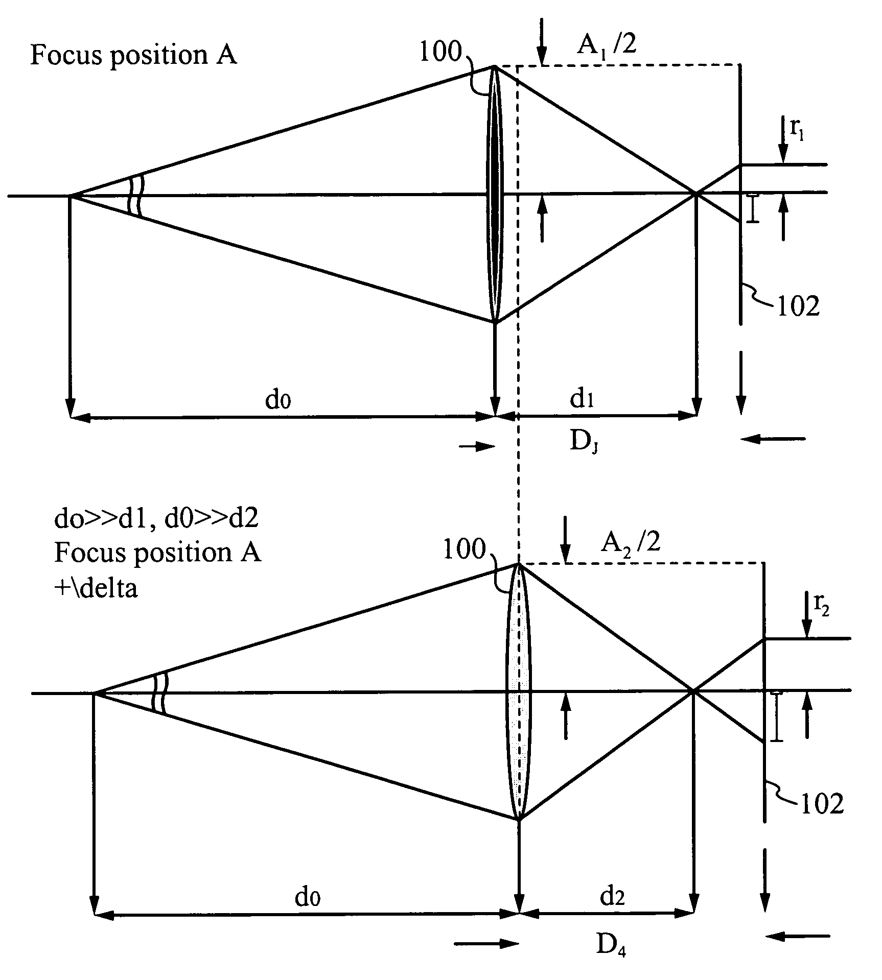
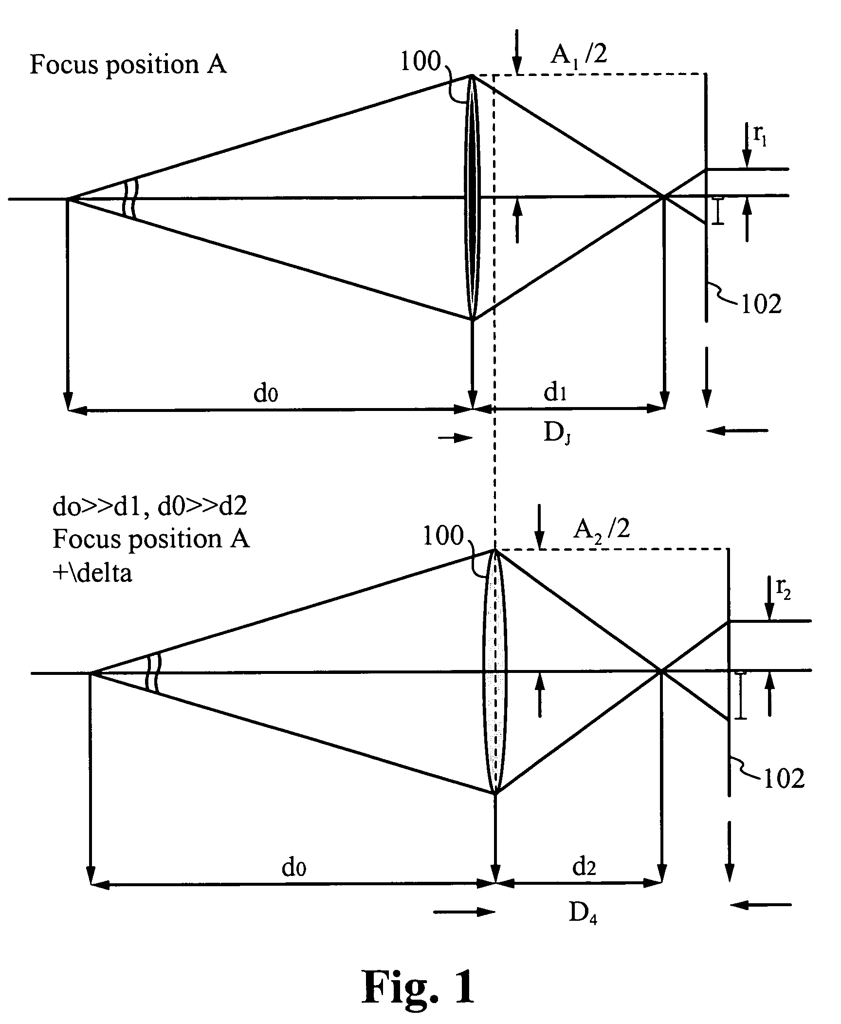
[0023]FIG. 1 illustrates an example of a lens 100 in a first position and in a second position to generate two images with different blur quantities on a sensor 102. With the lens 100 in focus position A, the distance from a scene (not shown) to the lens 100 is the distance d0 and the distance between the lens and the focal point is the distance d1, where the distance d0 is much greater than the distance d1. The distanc...


PUM


Abstract

A method of and an apparatus for determining a depth map utilizing a movable lens and an image sensor are described herein. The depth information is acquired by moving the lens a short distance and acquiring multiple images with different blur quantities. An improved method of simulating gaussian blur and an approximation equation that relates a known gaussian blur quantity to a known pillbox quantity are used in conjunction with a non-linear blur difference equation. The blur quantity difference is able to be calculated and then used to determine the depth map. Many applications are possible using the method and system described herein, such as autofocusing, surveillance, robot / computer vision, autonomous vehicle navigation, multi-dimensional imaging and data compression.

Description

FIELD OF THE INVENTION[0001]The present invention relates to the field of imaging. More specifically, the present invention relates to improved autofocusing.BACKGROUND OF THE INVENTION[0002]A variety of techniques for generating depth maps and autofocusing on objects have been implemented in the past. One method conventionally used in autofocusing devices, such as video cameras, is referred to a hill-climbing method. The method performs focusing by extracting a high-frequency component from a video signal obtained by an image sensing device such as a CCD and driving a taking lens such that the mountain-like characteristic curve of this high-frequency component is a maximum. In another method of autofocusing, the detected intensity of blur width (the width of an edge portion of the object) of a video signal is extracted by a differentiation circuit.[0003]A wide range of optical distance finding apparatus and processes are known. Such apparatus and processes may be characterized as ca...

Claims


Application Information

Patent Timeline
Patent Type & Authority Patents(United States)
IPC IPC(8): G06F9/40
CPCG03B3/02G02B27/0075G03B13/30
Inventor WONG, EARL Q.NAKAMURA, MAKIBIKUSHIDA, HIDENORITRITEYAPRASERT, SOROJ
Owner SONY CORP
Why Eureka
Try Eureka