
Filter

a filter and filter body technology, applied in the field of filters, can solve the problems of large amount of adhesive, and achieve the effect of preventing defects and good shatter resistan

Inactive Publication Date: 2010-05-11
MANN HUMMEL GMBH
View PDF18 Cites 7 Cited by
  • Summary
  • Abstract
  • Description
  • Claims
  • Application Information

AI Technical Summary

Benefits of technology

This solution reduces material costs, simplifies production, maintains the filtering surface area, and enhances fluid flow by eliminating adhesive usage and curing times, while enabling efficient disposal and improved dimensional stability of the filter medium.

Problems solved by technology

This adhesive fills the volume formed between the corrugation peaks and the filter sheet, which requires a large amount of adhesive.

Method used


Image

  • Filter
  • Filter
  • Filter

Examples


Embodiment Construction

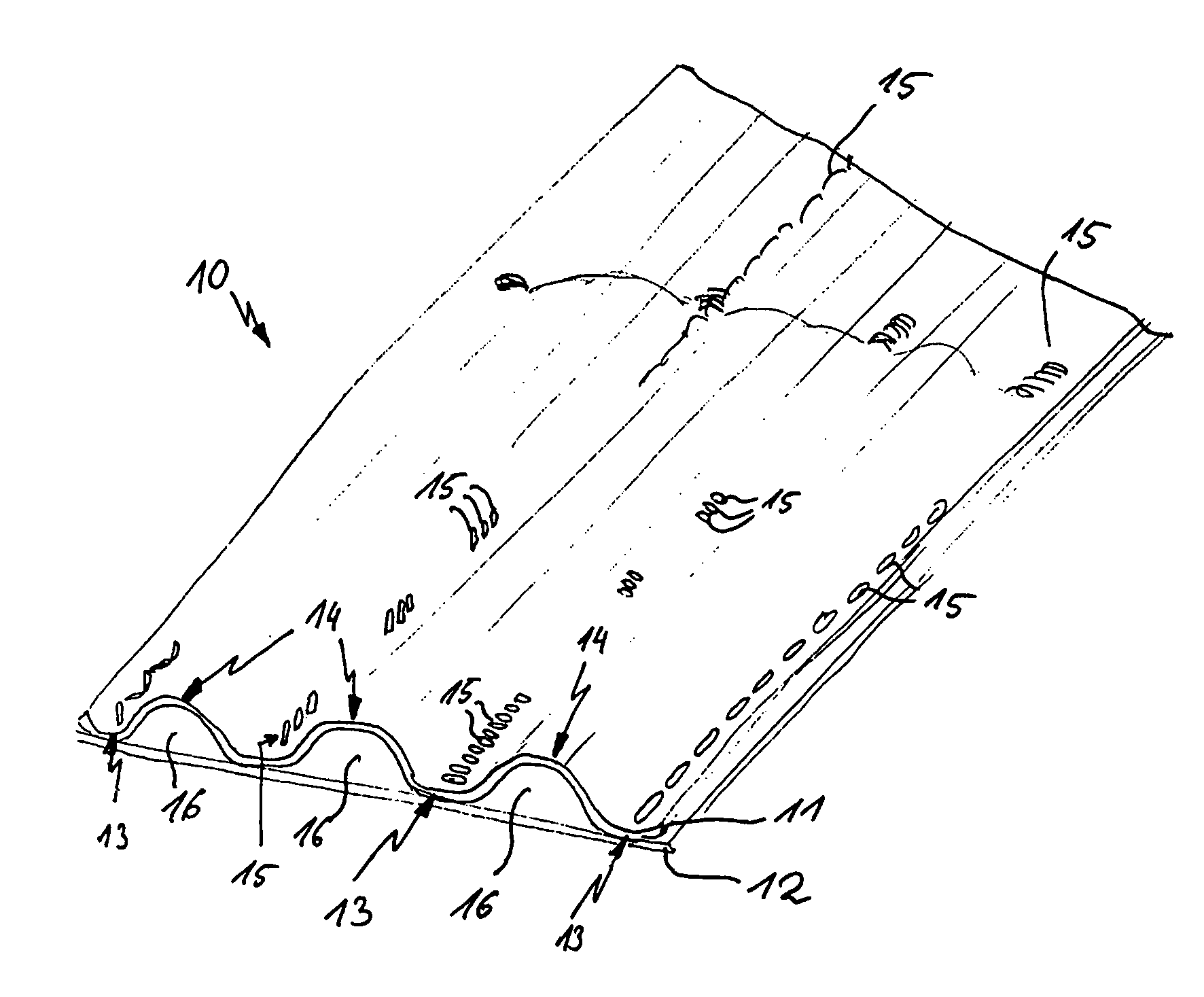
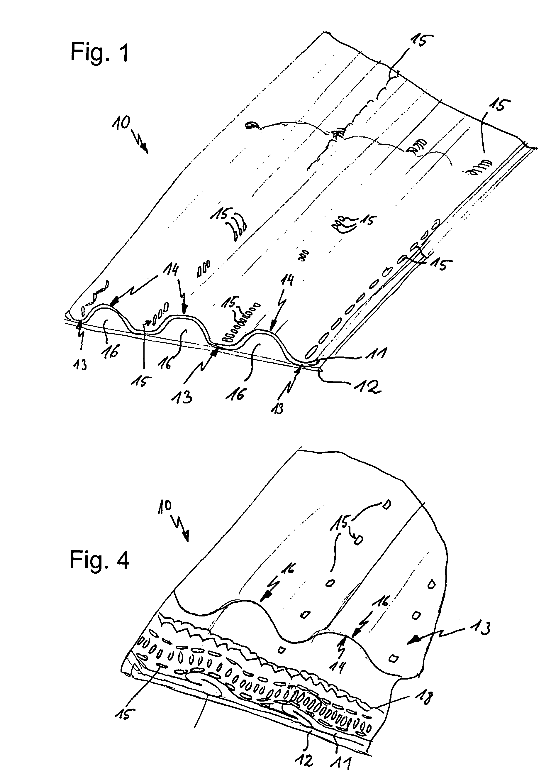
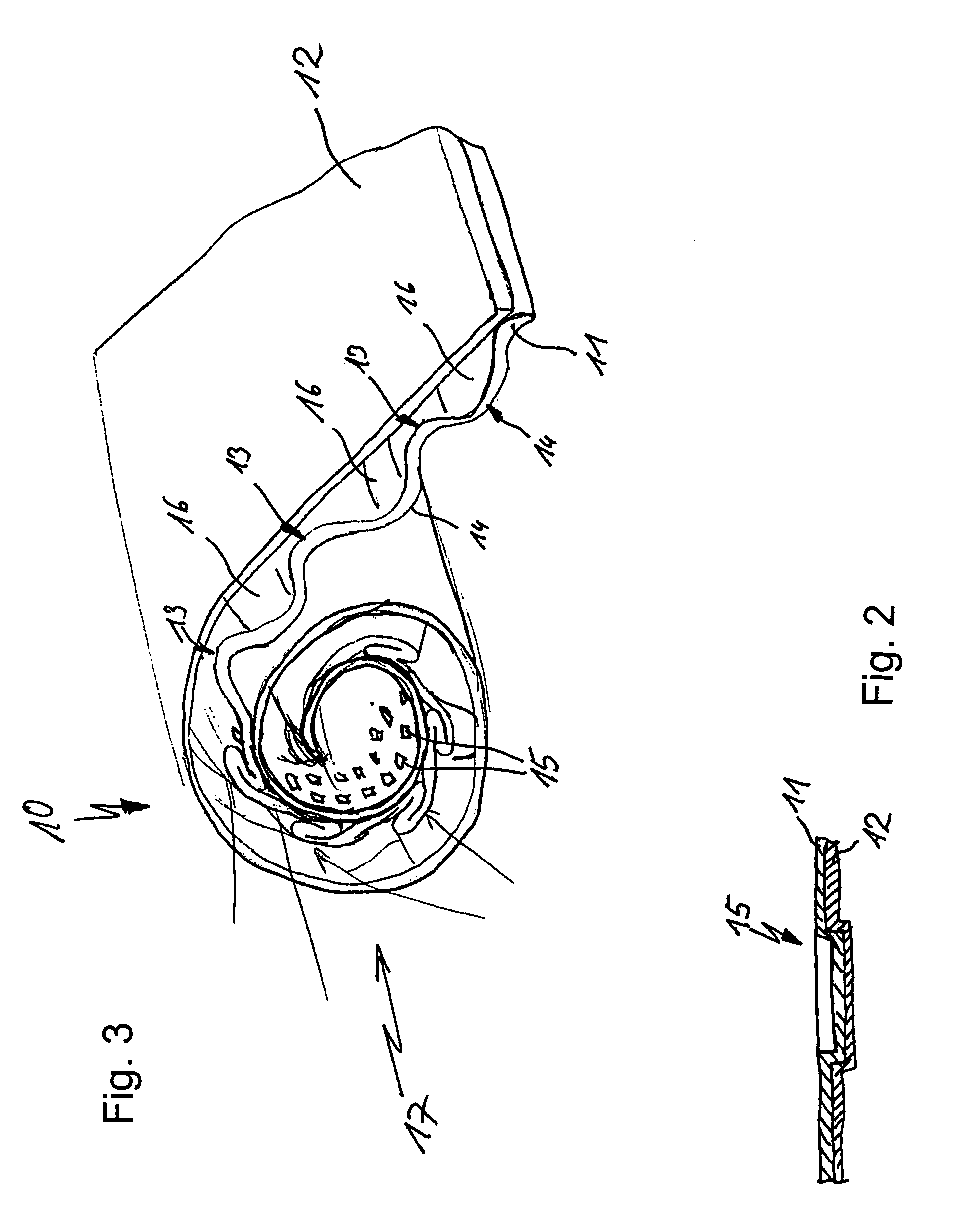
[0028]FIG. 1 is a detail perspective view of a filter medium 10, which depicts a partial manufacturing step. The filter medium 10 shown in this view will be further processed in a subsequent step. The filter medium 10 comprises a corrugated filter layer 11 and a flat filter sheet 12. Both filter strata 11, 12 are formed of the same dimensionally stable cellulose paper. The corrugated filter layer 11 has valleys 13 and peaks 14. The valleys 13 are connected to the flat filter sheet 12 by embossing points 15, so that the filter layer 11 is fixed to the filter sheet 12. The embossing points 15 are disposed in a line only in partial areas along the valley floor, which is the lowest point of the valley 13. Between the peaks 14 and the filter sheet 12, parallel-extending channels 16 are formed. Since the embossing points 15 do not form a sealing connection between the filter strata 11, 12, volume flows are able to pass from one channel 16 to the next channel 16 extending parallel thereto....


PUM

PropertyMeasurementUnit
porosityaaaaaaaaaa
corrugationaaaaaaaaaa
volumeaaaaaaaaaa

Abstract

A filter composed of a filter medium (10) formed from a corrugated filter layer (11) and a flat filter sheet (12) which are interconnected by embossing points (15). This eliminates the need for an additional joining agent. Production of the filter is simplified because no additional materials are required to be supplied or cured.

Description

BACKGROUND OF THE INVENTION[0001]The invention relates to a filter comprising a spirally wound filter medium formed from a corrugated filter layer and a flat filter sheet for separating particles from a fluid stream. In a preferred aspect the invention relates to a diesel particle filter for separating particles from the exhaust stream of an internal combustion engine.[0002]Filters having a spirally wound filter medium are known in the art. The filter medium is formed from a corrugated filter layer and a flat filter sheet. The corrugated filter layer has corrugation valleys and peaks. To connect the filter layer to the filter sheet, the corrugation valleys are glued to the filter sheet. Thus, channels are formed between the corrugation peaks and the filter sheet. As the filter medium is wound, channels are also formed between the corrugation valleys and the filter sheet wound on top of them. The end faces of the channels are alternately closed, so that the fluid to be cleaned can fl...

Claims


Application Information

Patent Timeline
Patent Type & Authority Patents(United States)
IPC IPC(8): B01D39/06B01D24/00B01D39/14B01D50/00B01J23/00F01N3/00F01N3/08F01N3/10
CPCB01D46/0001B01D46/527B01D2279/30B01D2265/04
Inventor LINHART, JOCHENFRANZ, ANDREAS
Owner MANN HUMMEL GMBH
Learn More