

Output driver circuit with output preset circuit and controlling method thereof having lower power consumption
a technology of output preset circuit and output driver circuit, which is applied in the direction of pulse technique, oscillation generator, reliability increasing modifications, etc., can solve the problems of high power consumption, achieve low switching noise, reduce power consumption, and read out speed high
- Summary
- Abstract
- Description
- Claims
- Application Information
AI Technical Summary
Benefits of technology
Problems solved by technology
Method used
Image

Examples
Embodiment Construction
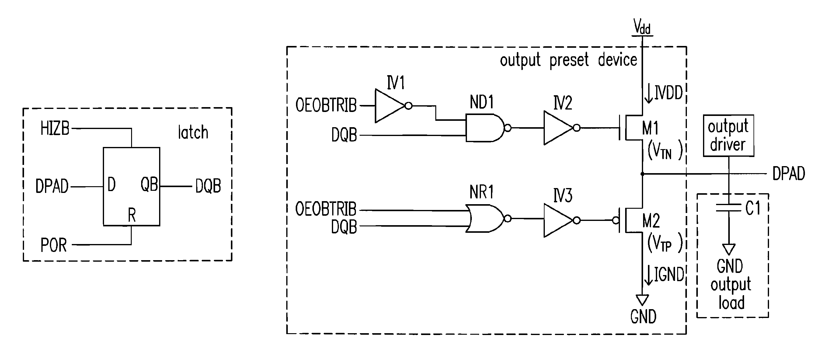
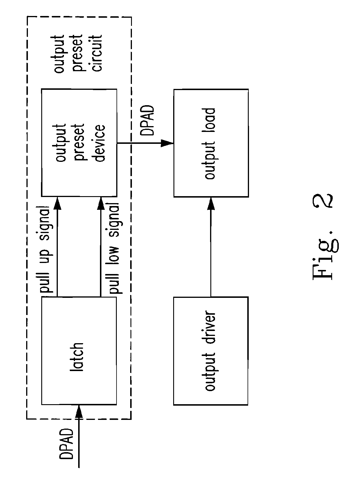
[0032]Please refer to FIG. 2, which shows a block diagram of an output driver circuit of the present invention. The provided output driver circuit of the present invention includes an output preset circuit, an output driver, and an output load. The output preset circuit includes a latch, which receives a voltage of the output load, DPAD, and generates a pull up signal and a pull low signal, and an output preset device, which is in one of the first status that it receives the pull up signal and pulls up the voltage of the output load, DPAD, from a ground level (e.g., GND(0)) to a first level (e.g., a difference between a power voltage and a threshold voltage of a NMOS, Vdd−VTN) and a second status that it receives the pull low signal and pulls low the voltage of the output load, DPAD from a power voltage (e.g., Vdd) to a second level (e.g., VTP, where VTP is a threshold voltage of a PMOS) during a preset on phase. The output driver is employed to pull up the voltage of the output loa...
PUM
 Abstract
Description
Claims
Application Information