Terminal device and real-time clock control method therefor enabling preservation of clock/calendar information and high information readout speed

Inactive Publication Date: 2005-08-30
LENOVO INNOVATIONS LTD HONG KONG
View PDF3 Cites 8 Cited by
  • Summary
  • Abstract
  • Description
  • Claims
  • Application Information

AI Technical Summary

Benefits of technology

[0008]It is therefore the primary object of the present invention to provide a terminal device and a real-time clock control method for the terminal device by whic

Problems solved by technology

However, if failure or abnormality such as a power cut occurred to the built-in microcomputer itself, the clock/calendar function of the built-in RTC might be impaired due to the effect of the failure.
However, in such composition employing the built-in RTC, power source pins and ground pins, power consumption is necessitated to be higher in comparison with the case where an external special-purpose RTC is employ

Method used


Image

  • Terminal device and real-time clock control method therefor enabling preservation of clock/calendar information and high information readout speed
  • Terminal device and real-time clock control method therefor enabling preservation of clock/calendar information and high information readout speed
  • Terminal device and real-time clock control method therefor enabling preservation of clock/calendar information and high information readout speed

Examples


first embodiment

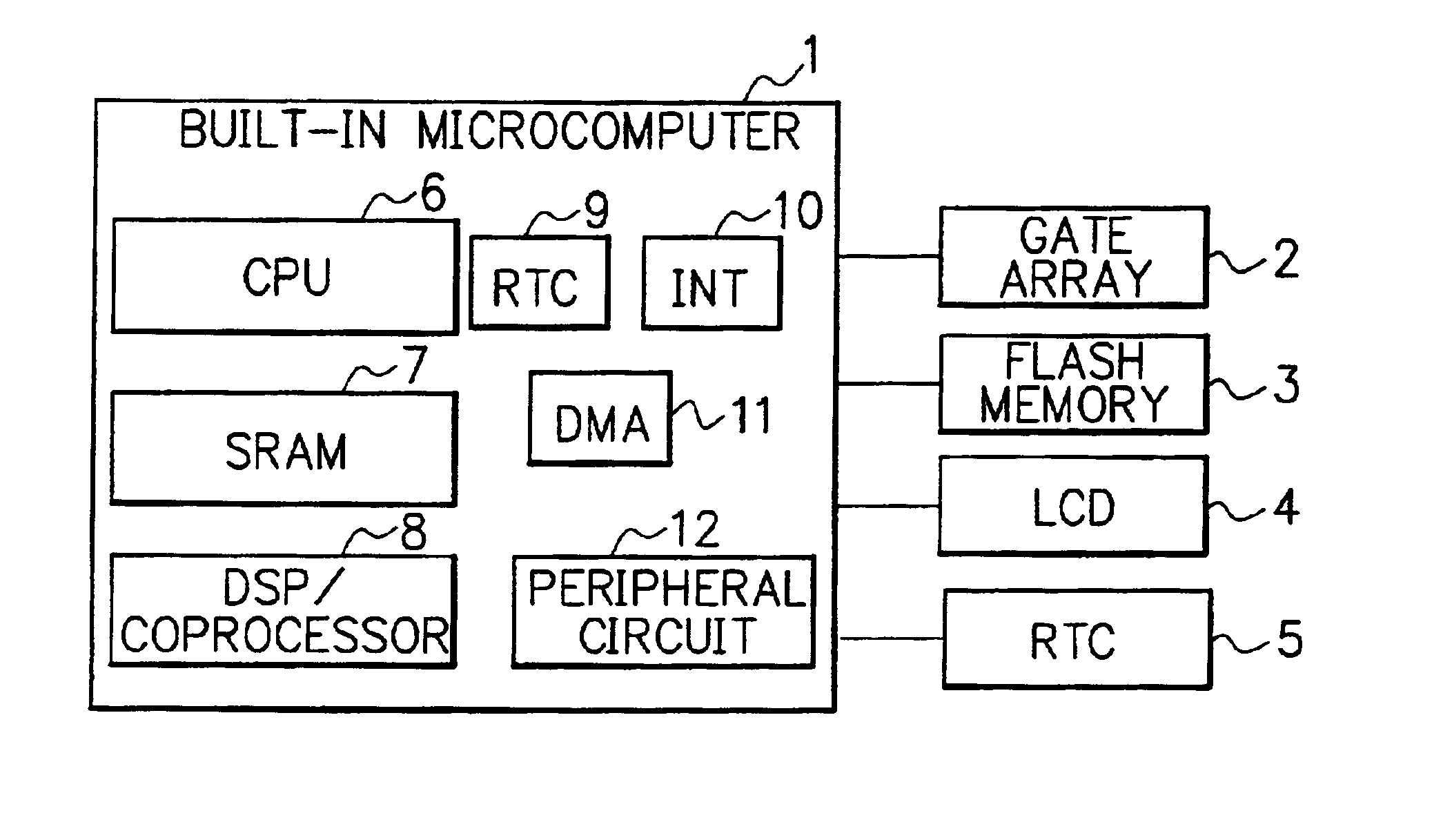
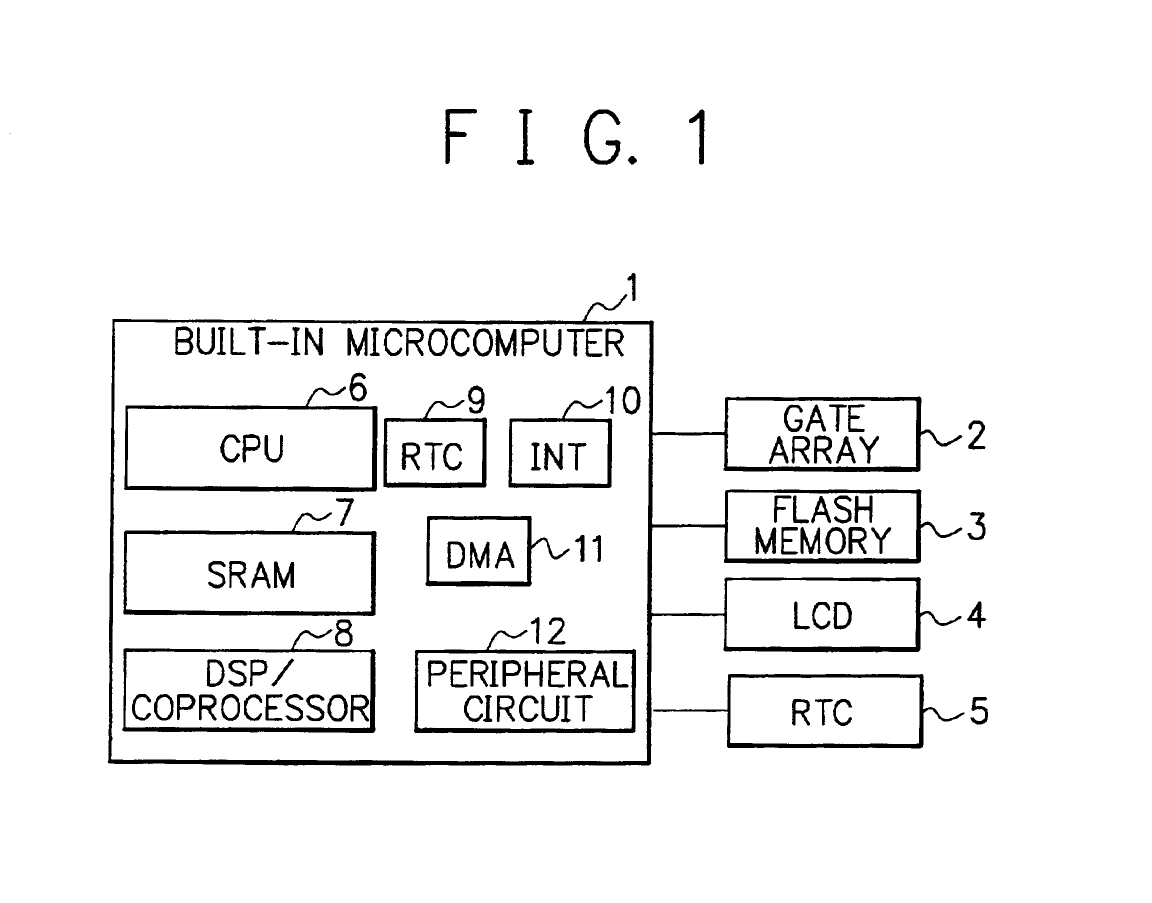
[0040]FIG. 1 is a block diagram showing the composition of the main part of a mobile terminal having an RTC (Real-Time Clock) function in accordance with the present invention. The mobile terminal of FIG. 1 utilizes a built-in microcomputer having a built-in RTC, and the clock / calendar function of the built-in RTC is maintained and preserved by use of an external RTC which is provided outside the built-in microcomputer. The external RTC is powered by a power source that is different from that of the built-in microcomputer.

[0041]The built-in microcomputer 1 shown in FIG. 1 includes a CPU (Central Processing Unit) 6 for controlling the whole of the mobile terminal, an SRAM (Static RAM) 7 which is used for temporarily storing control data etc., a DSP (Digital Signal Processor) or coprocessor 8 for carrying out multimedia data processing, and an RTC (Real-Time Clock) 9 for holding clock / calendar information and giving the information to the CPU 6 etc.

[0042]The built-in microcomputer 1 f...

second embodiment

[0064]FIG. 4 is a block diagram showing the composition of the main part of a mobile terminal in accordance with the present invention, in which the same reference characters as those of FIG. 1 designate the same or corresponding parts to those of FIG. 1 and thus repeated description thereof is omitted for brevity.

[0065]The key feature of the mobile terminal of the second embodiment is the indirect connection between the built-in microcomputer 1 and the external RTC 5 via a gate array, a CPU or the like (hereafter, referred to as a “gate array / CPU 41”). On each of signal lines 43 (between the built-in microcomputer 1 and the gate array / CPU 41) and 42 (between the gate array / CPU 41 and the external RTC 5), data is transferred by means of serial communication.

[0066]FIG. 5 is a flow chart showing a detailed procedure for a real-time clock function of the mobile terminal of the second embodiment. In a step S51 of FIG. 5, the CPU 6 judges whether or not the sleep mode of the mobile termi...

third embodiment

[0071]FIG. 6 is a block diagram showing the composition of the main part of a mobile terminal in accordance with the present invention, in which the same reference characters as those of FIG. 1 designate the same or corresponding parts to those of FIG. 1 and thus repeated description thereof is omitted for brevity.

[0072]The mobile terminal of the third embodiment is characterized by an RTC 63 which is formed in a gate array or FPGA (Field Programmable Gate Array) (hereafter, referred to as a “gate array / FPGA 61”) which is connected to the built-in microcomputer 1 via a signal line 62. The RTC 63 can also be regarded as an external RTC of the built-in microcomputer 1.

[0073]FIG. 7 is a flow chart showing a detailed procedure for a real-time clock function of the mobile terminal of the third embodiment. The procedure of FIG. 7 is a little different from that of FIG. 5 (second embodiment) in that the CPU 6 of the third embodiment gives an instruction to the gate array / FPGA 61 via the si...


PUM


Abstract

A terminal device such as a mobile terminal is provided with two real-time clocks which are powered by different power sources: a first real-time clock which is built in a control section (built-in microcomputer 1, for example) of the terminal device; and a second real-time clock which is provided outside the control section. At power-on of the mobile terminal or on recovery from failure such as a power cut, clock/calendar information is read out from the second real-time clock and is set to the first real-time clock, and thereafter, the control section obtains the clock/calendar information from the first real-time clock. The second real-time clock is connected to the control section directly by a signal line or via a functional device, or the second real-time clock is built in a functional device which is connected to the control section. By such composition and operation, the clock/calendar information can be maintained reliably and correctly even if failure occurred to the control section. The readout of the clock/calendar information is carried out usually from the first real-time clock (built-in RTC), therefore, high readout speed can be realized.

Description

BACKGROUND OF THE INVENTION[0001]The present invention relates to a terminal device having a real-time clock function and a method for controlling the real-time clock.DESCRIPTION OF THE RELATED ART[0002]The clock / calendar function or clock / calendar display function (a function for holding and displaying clock (time) information and calendar (date) information) of mobile terminals such as portable cellular phones is generally realized by use of an externally-added special-purpose element or device for RTC (Real-Time Clock) or by use of a built-in RTC of a microcomputer which is installed in the mobile terminal (hereafter, referred to as a “built-in microcomputer”).[0003]Especially in the case where the built-in RTC of the built-in microcomputer is used, high readout speed of the clock / calendar can be realized without the need of extra space for the installation of the RTC.[0004]However, if failure or abnormality such as a power cut occurred to the built-in microcomputer itself, the c...

Claims


Application Information

Patent Timeline
IPC IPC(8): G06F1/14G04C9/04G04G3/00G04G5/00H04L7/00
CPCG06F1/14
Inventor YANO, MASATOSHI
Owner LENOVO INNOVATIONS LTD HONG KONG
Why Eureka
Try Eureka