Loader

a technology of loader and load plate, which is applied in the field of loader, can solve the problems of vehicle overturning and unsafe load conditions

Active Publication Date: 2010-05-18
DEERE & CO
View PDF7 Cites 7 Cited by
  • Summary
  • Abstract
  • Description
  • Claims
  • Application Information

AI Technical Summary

Benefits of technology

[0007]According to the invention, a loader of the kind mentioned by way of introduction is configured in such a way that means for varying the control pressure are connected to at least one control pressure line running between the actuating device and the control device, by which means, depending on a sensor signal supplied by the sensor, the control pressure generated by the actuating device is capable of being varied. The operability of the hydraulically controlled control device is influenced via the means for varying the control pressure in such a way that the pressure in the control pressure line is reduced, so that the manipulating variable at the control device and thus the volumetric flow of hydraulic fluid for the hydraulic cylinder regulated via the control device is reduced. The control pressure in the control pressure line is reduced to an increasing extent in this way, the closer a critical value for the load condition is approached, which value is set by the electronic control unit. In order to prevent an operator from being able to bring the vehicle into an unsafe condition, which might ultimately result in the overturning of the vehicle, the functions of the hydraulic cylinder are initially slowed down in this way and are then finally brought completely to a halt.
[0010]It is thus possible to restrict the movements of the extension arm in such a way that the vehicle is not able to get into a dangerous operating condition, in conjunction with which the operator, in addition to the warning signals which are generated anyway in the cab of the loader, will be made aware of the fact that, in spite of its adjustment default, the extension arm is moving increasingly slowly until it comes to a halt.
[0012]The loader is preferably configured as a telescopic loader, in conjunction with which the extension arm is capable of being varied via a first hydraulic cylinder in respect of its angle of attack and via a second hydraulic cylinder in respect of its length, in conjunction with which a third hydraulic cylinder may be provided, with which an implement arranged on the extension arm is capable of being caused to pivot. Thus, for example, the tilting back of a loading shovel filled with material can also lessen a critical load condition, but without the extension arm being moved. In any case, the overpressure valves or pressure reduction valves arranged in the control pressure lines of the control devices provide for a slow execution of the movements determined by the operating person, so that no disruptive inertia mass effects of the load material or of the extension arm occur, which can then provoke overturning of the loader in the vicinity of the threshold value range.

Problems solved by technology

Unsafe load conditions arise, for example, when the vehicle overturns over the front axle as the result of a forward shift in the center of mass.
In systems of this kind, it is sensible not to arrest the movements of an extension arm too abruptly, as this can lead to overturning of the vehicle due to the inertia of the load and the extension arm.
For hydro-mechanical systems with mechanically controlled control devices, the characterizing features disclosed in WO 2004 / 007339 A1 do not find an application, because a hydraulically pilot-controlled system intervention is not possible in a controlled manner by such simple means in the functions, due to the absence of suitable electronics.

Method used


Image

  • Loader
  • Loader
  • Loader

Examples


Embodiment Construction

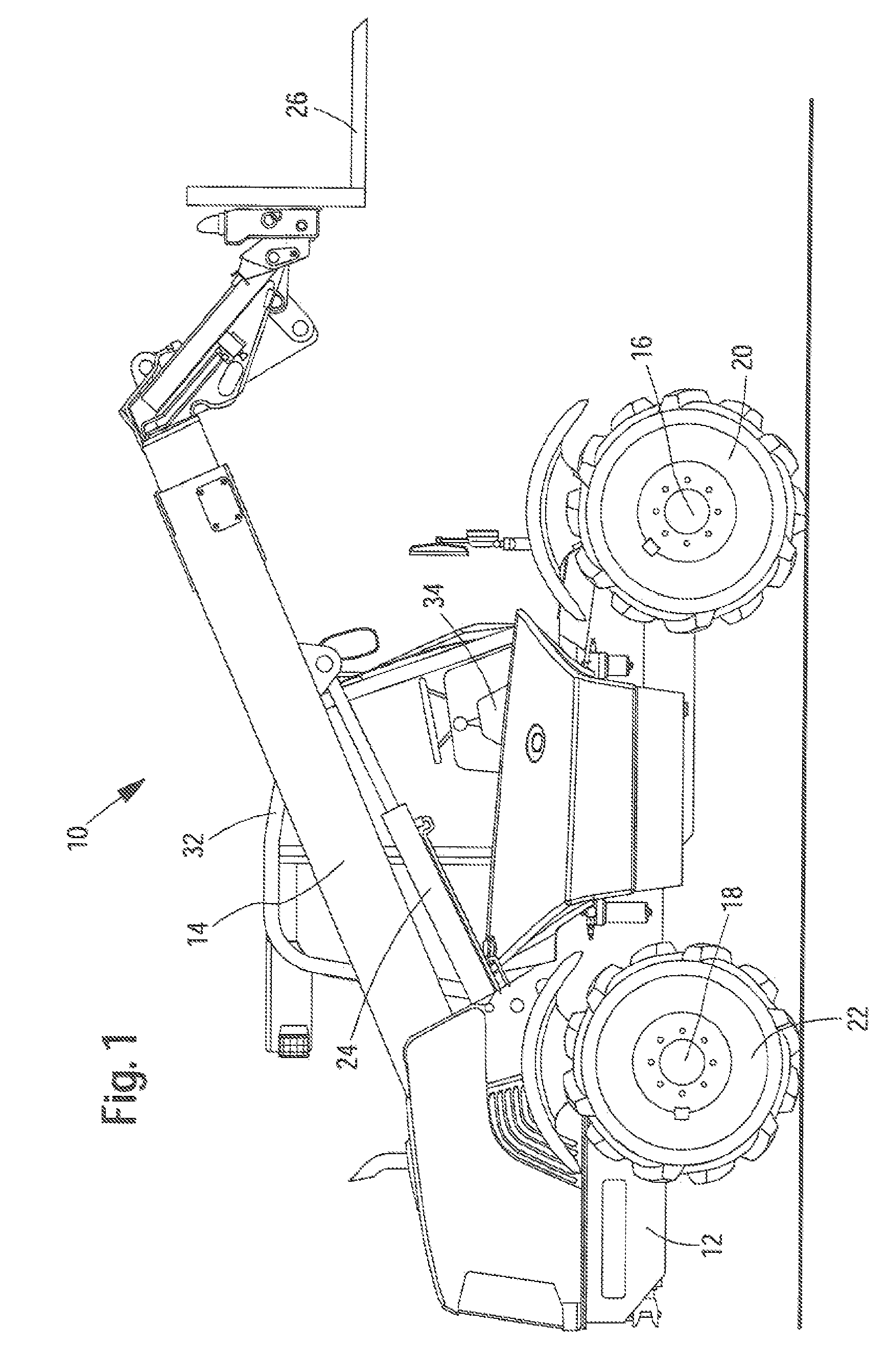
[0023]Illustrated in FIG. 1 is a loader 10 in the form of a telescopic loader. The telescopic loader 10 exhibits a frame 12, to which an extension arm 14 is linked The frame 12 is supported by a front axle 16 and by a rear axle 18 with corresponding front and rear sets of wheels 20 and 22, respectively.

[0024]The extension arm 14 is configured as a telescopic extension arm and is adjustably linked via a hydraulic cylinder 24 in respect of its angle of attack in relation to the frame 12. A second hydraulic cylinder (not illustrated) is arranged in the interior of the extension arm 14 and permits the retraction and / or extension (telescoping) of the extension arm. A third hydraulic cylinder (not illustrated) is arranged on the free end of the extension arm 14 in the interior and permits the oscillation and / or tilting of a loading implement 26.

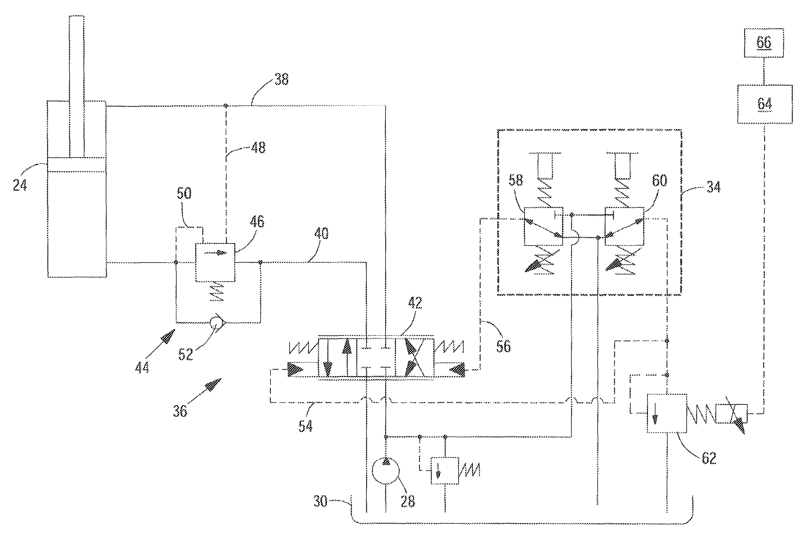
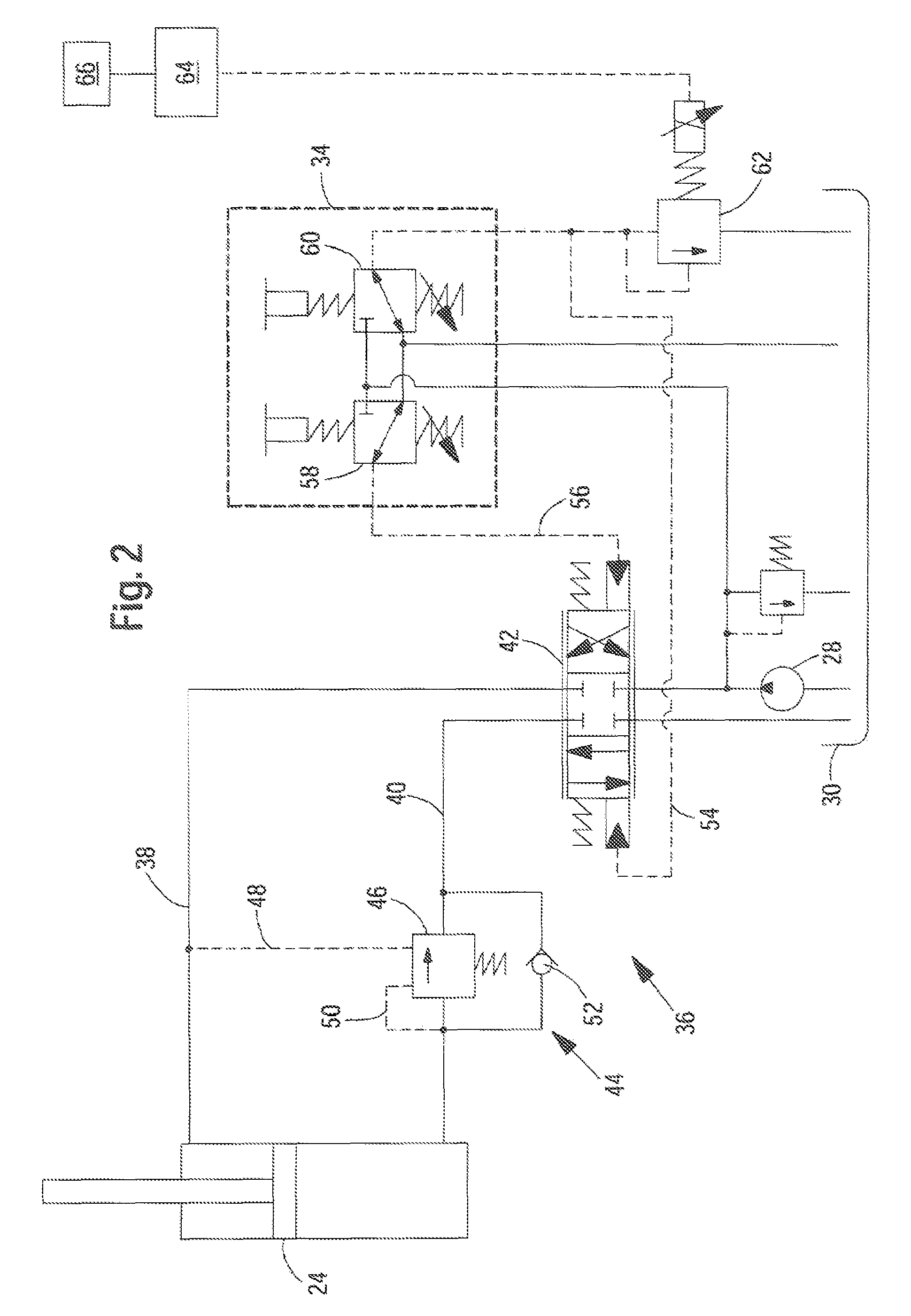
[0025]The loader 10 possesses a hydraulic source 28 and a hydraulic tank 30, which are arranged underneath the vehicle bodywork and serve the purp...


PUM


Abstract

A loader includes a hydraulically operated extension arm, a load sensor for monitoring the load condition on the loader and a hydraulic arrangement for actuation of the extension arm and / or an implement attached to the extension arm. The hydraulic arrangement exhibits at least one hydraulic cylinder with one supply line on the piston rod side and one supply line on the piston side. At least one hydraulically switchable control device is coupled between a source of fluid pressure and a hydraulic tank, on the one hand, and the supply lines on the other hand. An actuating device is coupled for routing control pressure to the control device via first and second control pressure lines. An electronic control unit is connected for effecting operation of a control pressure control device, which is coupled to at least one of the control pressure lines, in response to a load signal received from the load sensor so as to actuate the control device for achieving a slowed-down actuation of the hydraulic cylinder in conjunction with the onset of a critical load condition. Thus, a restriction of a volumetric flow is achieved in at least one of the supply lines coupled to the hydraulic cylinder.

Description

FIELD OF THE INVENTION[0001]The invention relates to a loader with a hydraulically actuated extension arm, a sensor for monitoring the load condition on the loader and a hydraulic arrangement for actuation of the extension arm and / or implement attached to the extension arm, the hydraulic arrangement exhibiting at least one hydraulic cylinder; at least one hydraulically actuated control device for controlling the at least one hydraulic cylinder, a hydro-mechanical actuating device for the generation of hydraulic control pressure signals for the at least one control device, a hydraulic source, a hydraulic tank and an electronic control unit.BACKGROUND OF THE INVENTION[0002]In the area of loaders, such as loading vehicles or telescopic loaders and the like, systems are previously disclosed which protect the vehicle from getting into an unsafe load condition. Unsafe load conditions arise, for example, when the vehicle overturns over the front axle as the result of a forward shift in the...

Claims


Application Information

Patent Timeline
Patent Type & Authority Patents(United States)
IPC IPC(8): B66C13/12
CPCB66F9/22B66F17/003F15B11/003E02F9/226F15B2211/50545
Inventor BITTER, MARCUSTUDOR, RICHARD
Owner DEERE & CO
Why Eureka
Try Eureka