
Angle grinder and angle grinder spindle-collet adaptor

Inactive Publication Date: 2010-05-18
LYERLY DENNIS J
View PDF34 Cites 7 Cited by
  • Summary
  • Abstract
  • Description
  • Claims
  • Application Information

AI Technical Summary

Benefits of technology

[0013]Exemplary embodiments of the present invention solve inadequacies of the prior art by providing an improved angle grinding operation. A first object of the invention is to allow flexibility of tooling. A second object of the invention is to improve ergonomics and operator comfort for two hand operation and better positioning of the grinder. Another object of the present invention is to enable a safer process by using a lower revolution per minute hand tool allowing safer tooling speeds. A further object of the invention is to provide possible cost savings, as an operator docs not have to purchase a separate die grinder and expensive air compressor to use die grinder tooling. Yet another object of the present invention is to permit flexibility of use in remote locations, since only one grinder would then be required and the need for an air hose to the work area is eliminated.

Problems solved by technology

Die grinders are usually pneumatic tools, and require an air compressor capable of providing supply air at a pressure of 90 pounds per square inch (PSI), or they are large, expensive 110 volt AC powered tools.

Method used


Image

  • Angle grinder and angle grinder spindle-collet adaptor
  • Angle grinder and angle grinder spindle-collet adaptor
  • Angle grinder and angle grinder spindle-collet adaptor

Examples


Embodiment Construction

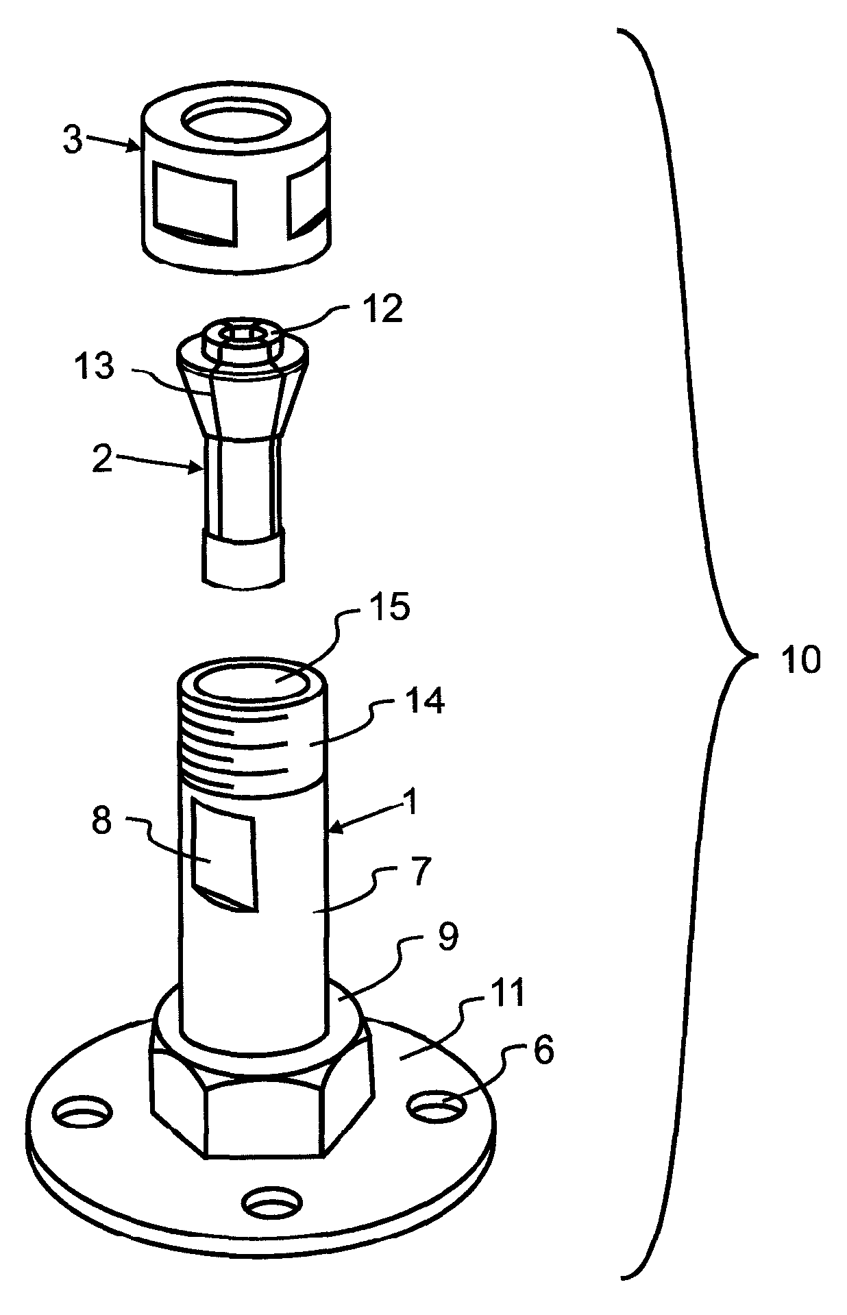
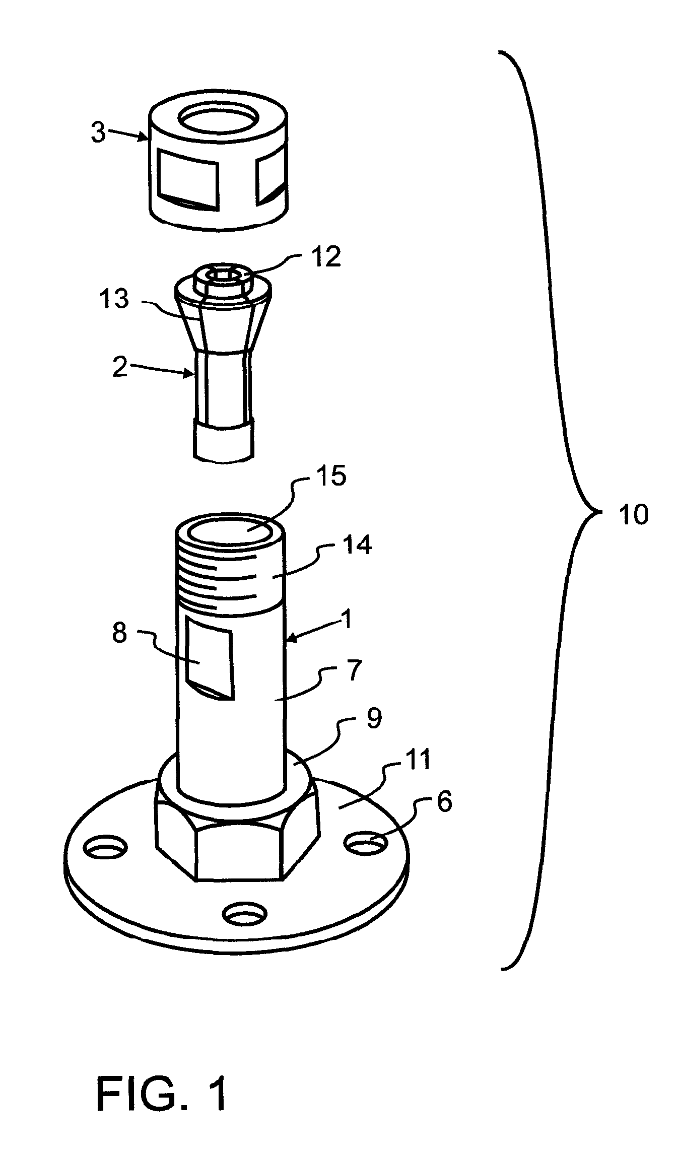
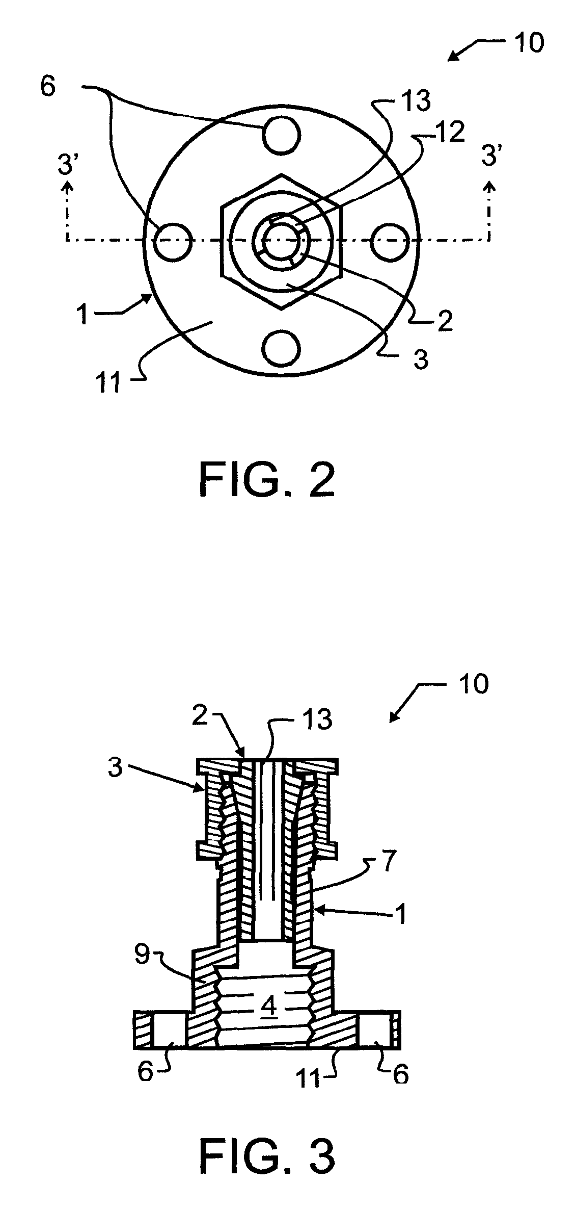
[0036]For the purposes of the present disclosure, a collet is defined as a slotted or otherwise radially deformable generally cylindrical clamp, which, when tightly engaged with an interior of a sleeve, will likewise tightly engage and hold a generally cylindrical shank, device or part such as a tool or work piece. One or both of the collet or sleeve may be tapered. In the art, most commonly both surfaces are tapered, which helps to ensure proper alignment and smooth clamping. The source of driving force to cause the collet to tightly engage with the tapered interior of a sleeve is most commonly a collet nut which has a relatively larger opening on a first end adapted to pass circumferentially about the collet. The first end is threaded, and engages with exterior threads on the sleeve. A second opposed end of the collet nut is of relatively smaller open diameter, such that the collet will not pass through, while a tool or work piece may. Various types of collets are known in the too...


PUM


Abstract

A simple three piece machined steel Collet-Spindle Adaptor for angle grinders includes a hat-shaped base having interior threading for coupling with a threaded spindle on an angle grinder. A sleeve extends therefrom and has an interior surface which engages with a collet. The preferred adaptor converts an angle grinder to accept die grinding tools and other similar tools, thereby providing flexibility of tooling, flexibility of application and work area, ergonomics in operator comfort by providing two hand operation, safety in lower operating tool speed, and reduced cost as an additional die grinder and expensive air compressor are not required. Simple machined design allows rapid change over and small size allows easy toolbox storage.

Description

CROSS REFERENCE TO RELATED APPLICATIONS[0001]This application claims priority to U.S. provisional application Ser. No. 60 / 806,453 filed Jun. 30, 2006 of the same title and naming the present inventor, the contents which are incorporated herein by reference in entirety.BACKGROUND OF THE INVENTION[0002]1. Field of the Invention[0003]This invention pertains generally to cutting or material removal by use of a rotating axially moving tool, and more particularly to tool supports used therewith. More particularly, this invention relates to angle and die grinders, and in a most specific manifestation to an adaptor which allows the use of ⅛ inch and ¼ inch arbor shaft die grinder tooling with electric angle grinders.[0004]2. Description of the Related Art[0005]Angle and die grinders are used primarily in the removal of material by grinding, polishing, and sanding surface imperfections, welds, oxidation, etc. This process is achieved by utilizing flat sanding pads, flat type 27 grinding whee...

Claims


Application Information

Patent Timeline
IPC IPC(8): B24B27/08
CPCB23B31/20B24B45/00B24B23/028Y10T279/17427B23B31/20125
Inventor LYERLY, DENNIS J.
Owner LYERLY DENNIS J
Learn More